There are Ansible modules for configuring most of the NSX-T platform components, but for certain configuration tasks it might be quicker (or even necessary) to GET/POST/PUT/PATCH/DELETE to the NSX-T REST API directly.
Now, in those situations you could use curl or Postman or any of the other REST API clients out there, but if you would actually prefer to stay within your Ansible system instead of doing “quick and dirties” that aren’t documented, traceable, or reusable, the “nsxt_rest” module could be an interesting alternative.
The “nsxt_rest” module is part of the official Ansible NSX-T modules that is maintained by VMware. The module gives you direct access to the NSX-T REST API and basically lets you configure anything you can configure through the NSX-T REST API. In other words, this is the only module you will ever need. 😉
Example
I recently had to test and re-test Tier-0 route filtering settings in different environments. I used the opportunity to create a simple Ansible Playbook with some tasks using the “nsxt_rest” module. This Playbook is maintained on GitHub, but I will post a static version of it here just for reference:
---
- hosts: localhost
  name: ConfigureEgress.yml
  vars:
    NsxManagerAddress:     pod-220-nsxt-lm-1.sddc.lab                  # FQDN or IP address of your NSX Manager
    NsxManagerUser:        admin                                       # NSX Manager username
    NsxManagerPassword:    VMware1!VMware1!                            # NSX Manager password
    Tier0:                 T0-Gateway-01                               # Name of the Tier-0 Gateway
    LocalAs:               65001                                       # ASN on the NSX side
    RemoteAs:              65000                                       # ASN on the physical router side
    Prefix1:               any                                         # Name of the "Any" prefix
    Prefix2:               default-route                               # Name of the "Default Route" prefix
    RouteMapIn:            rm-in                                       # Name of the route map that is applied to the "In" filter
    RouteMapOut:           rm-out                                      # Name of the route map that is applied to the "Out" filter
    NeighborID1:           101eeb51-c0e7-41b3-b56a-5d8df4c29226        # ID of BGP neighbor #1 entry that should be configured with the filters
    NeighborIP1:           10.203.236.1                                # IP address of BGP neighbor #1 that should be configured with the filters
    NeighborID2:           d56e1a6f-d125-448a-8753-ca4b53bbf4bc        # ID of BGP neighbor #2 entry that should be configured with the filters
    NeighborIP2:           10.203.237.1                                # IP address of BGP neighbor #2 that should be configured with the filters
  tasks:


    - name: Create prefix lists for "Any" and "Default Route"
      nsxt_rest:
        hostname: "{{ NsxManagerAddress }}"
        username: "{{ NsxManagerUser }}"
        password: "{{ NsxManagerPassword }}"
        validate_certs: false
        method: patch
        path: "/policy/api/v1/infra/tier-0s/{{ Tier0 }}/prefix-lists/{{ item.name }}"
        content:
          {
            "prefixes": [
                {
                    "network": "{{ item.network }}",
                    "action": "{{ item.action }}"
                }
            ]
          }
      loop:
        - { name: "{{ Prefix1 }}", network: "ANY", action: "PERMIT" }
        - { name: "{{ Prefix2 }}", network: "0.0.0.0/0", action: "PERMIT" }


    - name: Create route map for the "In" filter
      nsxt_rest:
        hostname: "{{ NsxManagerAddress }}"
        username: "{{ NsxManagerUser }}"
        password: "{{ NsxManagerPassword }}"
        validate_certs: false
        method: patch
        path: "/policy/api/v1/infra/tier-0s/{{ Tier0 }}/route-maps/{{ RouteMapIn }}"
        content:
          {
             "entries":[
                {
                   "prefix_list_matches":[
                      "/infra/tier-0s/T0-Gateway-01/prefix-lists/{{ Prefix1 }}"
                   ],
                   "set":{
                      "local_preference":90
                   },
                   "action":"PERMIT"
                },
                {
                   "prefix_list_matches":[
                      "/infra/tier-0s/T0-Gateway-01/prefix-lists/{{ Prefix2 }}"
                   ],
                   "set":{
                      "local_preference":80
                   },
                   "action":"PERMIT"
                }
             ]
          }


    - name: Create route map for the "Out" filter
      nsxt_rest:
        hostname: "{{ NsxManagerAddress }}"
        username: "{{ NsxManagerUser }}"
        password: "{{ NsxManagerPassword }}"
        validate_certs: false
        method: patch
        path: "/policy/api/v1/infra/tier-0s/{{ Tier0 }}/route-maps/{{ RouteMapOut }}"
        content:
          {
             "entries":[
                {
                   "prefix_list_matches":[
                      "/infra/tier-0s/T0-Gateway-01/prefix-lists/{{ Prefix1 }}"
                   ],
                   "set":{
                      "as_path_prepend":"{{ LocalAs }}",
                      "local_preference":100
                   },
                   "action":"PERMIT"
                }
             ]
          }


    - name: Add the filters to the BGP neighbor entries
      nsxt_rest:
        hostname: "{{ NsxManagerAddress }}"
        username: "{{ NsxManagerUser }}"
        password: "{{ NsxManagerPassword }}"
        validate_certs: false
        method: patch
        path: "/policy/api/v1/infra/tier-0s/{{ Tier0 }}/locale-services/{{ Tier0 }}_Locale_Services/bgp/neighbors/{{ item.neighbor }}"
        content:
          {
             "neighbor_address" : "{{ item.ip }}",
             "remote_as_num" : "{{ item.as }}",
             "in_route_filters":[
                "/infra/tier-0s/{{ Tier0 }}/route-maps/{{ RouteMapIn }}"
             ],
             "out_route_filters":[
                "/infra/tier-0s/{{ Tier0 }}/route-maps/{{ RouteMapOut }}"
             ],
             "route_filtering":[
                {
                   "enabled":true,
                   "address_family":"IPV4",
                   "in_route_filters":[
                      "/infra/tier-0s/{{ Tier0 }}/route-maps/{{ RouteMapIn }}"
                   ],
                   "out_route_filters":[
                      "/infra/tier-0s/{{ Tier0 }}/route-maps/{{ RouteMapOut }}"
                   ]
                }
             ]
          }
      loop:
        - { neighbor: "{{ NeighborID1 }}", ip: "{{ NeighborIP1 }}", as: "{{ RemoteAs }}" }
        - { neighbor: "{{ NeighborID2 }}", ip: "{{ NeighborIP2 }}", as: "{{ RemoteAs }}" }
This is looks very similar to using curl commands, except now it’s wrapped in an Ansible Playbook that I can easily check in to some version control system, share, and re-use. I think those are some pretty nice benefits.
During some research I did for a customer on how to trigger an action based on an error event in the SDDC, I built myself a lab and ended up with a concept that seems interesting enough to write some lines about on the blog.
High-Level
The diagram below illustrates the “solution” at a high-level:
No rocket science here. A system logs an event to Log Insight which generates an alert that triggers a Jenkins pipeline which remediates the system.
So what does setting this up look like? Must be pretty difficult? I thought so too, but let’s have a look at an example in this article.
Remediate The NSX-T Distributed Firewall
In this simple example the “system” is the NSX-T Distributed Firewall (DFW) Default Layer 3 Rule. This is the last rule in the DFW table which determines what to do with traffic that is not matching any other rules (Drop or Allow).
In our example we want traffic not being picked up by other DFW rules to be dropped and therefore the Default Layer 3 Rule is configured with a “Drop” action.
If for some reason the action is changed to “Allow”, we want it to automatically revert back to “Drop” as that is our desired/required state.
So there we have the use case for some event-driven automation.
Step 1 – Identify The Event And Construct A Log Insight Query
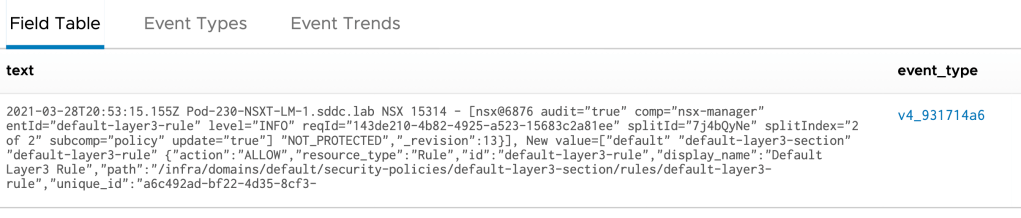
Before we can do anything meaningful we need to find the event that is logged when we change the firewall rule action to “Allow”. In this case the event in Log Insight looks like this:
Using this information we can build a reliable Log Insight query that will show us this event and nothing else. Reliable and consistent are keywords as we’re about to connect this query to automation and the last thing we want here are trigger happy false positives.
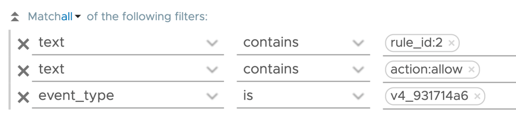
I’m fairly confident that the following Log Insight query is reliable enough for our example use case:
text contains rule_id:2 text contains action:allow event_type is v4_931714a6
Step 2 – Create Alert From Query
If the query comes back with a match, i.e, the DFW rule’s action has been changed to “Allow”, an alert should be activated. This alert is configured directly from the Log Insight Interactive Analytics interface where we also constructed our query.
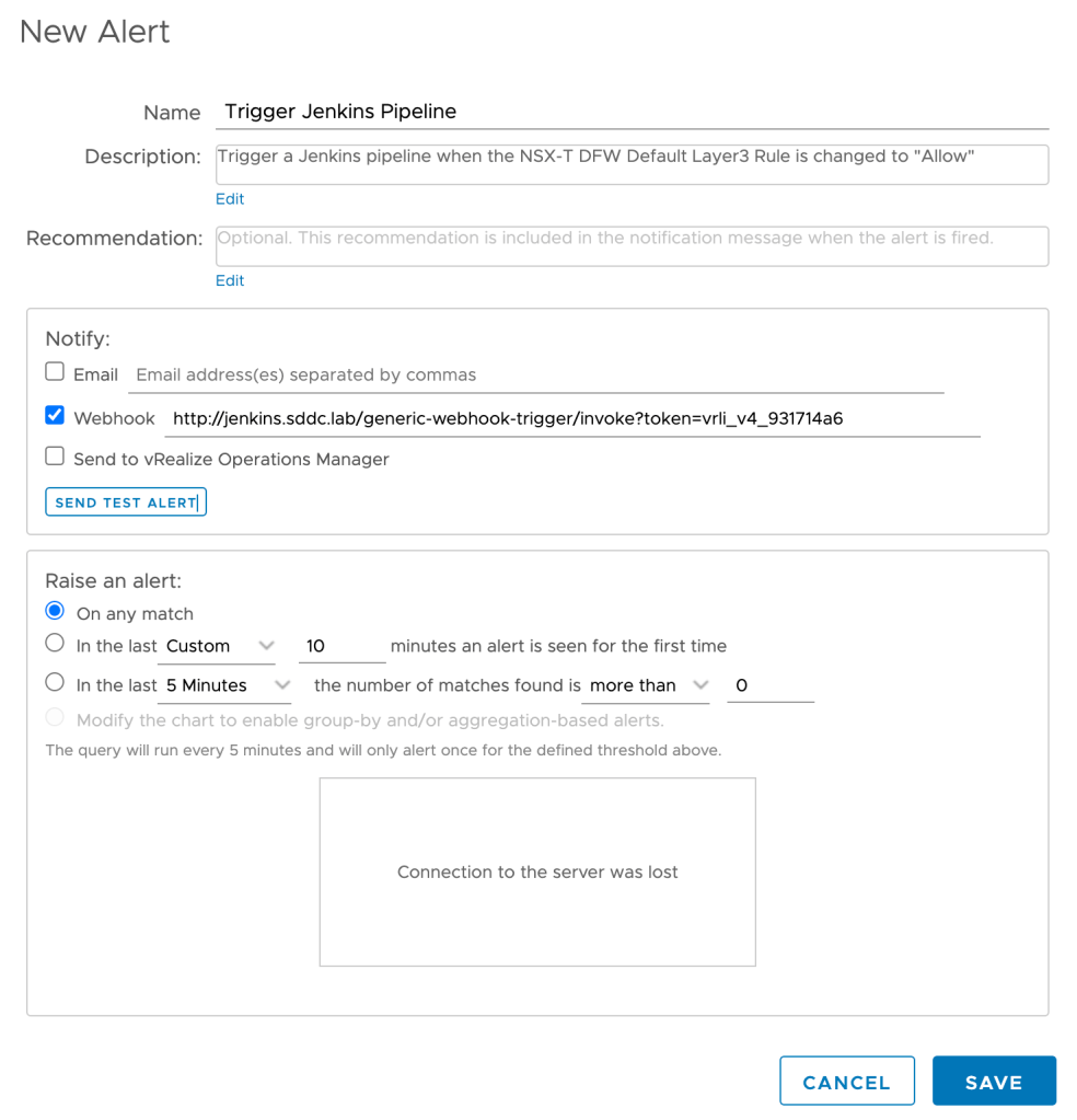
The alert I’m creating looks likes this:
As you can see I’m using a webhook to notify a Jenkins pipeline. We will look more at Jenkins in the coming steps. For now it’s good to understand that Log Insight will execute a HTTP POST request each time the defined query comes back with a match.
Step 3 – Configure Jenkins Pipeline Build Trigger
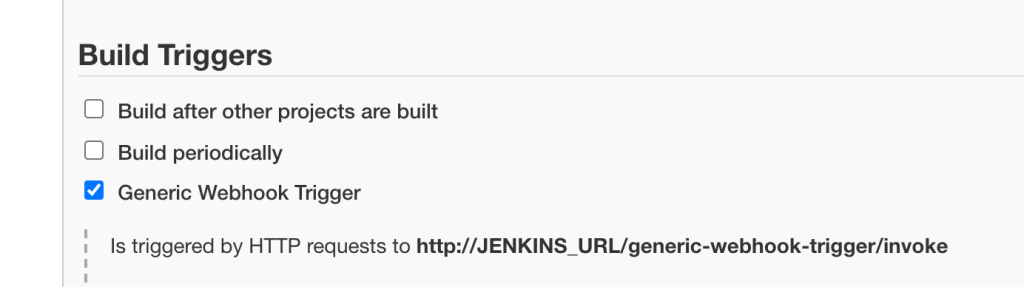
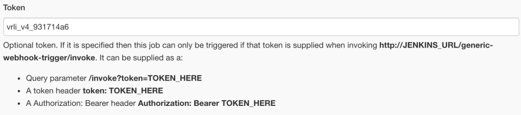
I decided to use the Generic Webhook Trigger plugin on Jenkins which extends the build triggers of a pipeline to allow easy triggering through HTTP requests (e.g. webhooks).
In our simple example very little configuration is required for the Generic Webhook Trigger configuration. Besides enabling it I’m adding a token to distinguish this build trigger from any others I might be creating:
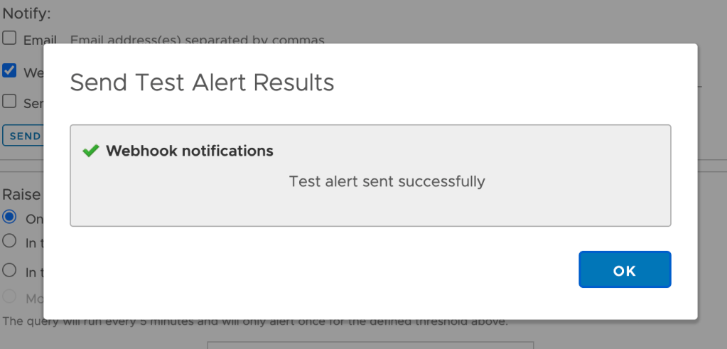
Back in Log Insight we can actually send a test alert to the webhook. This should result in the following message which indicates that Jenkins and specifically the webhook trigger are working:
Step 4 – Configure Jenkins Pipeline Script
The pipeline script contains the code that is executed to remediate our NSX-T DFW undesired state. NSX-T of course has a REST API which makes things relatively easy to configure.
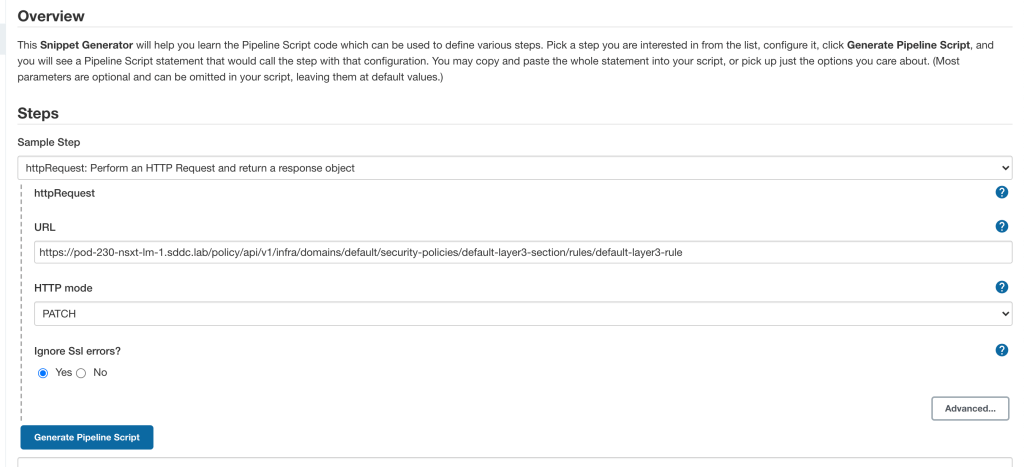
Using the Jenkins Pipeline Syntax and Snippet Generator for a httpRequest step, it was easy to put together a pipeline script that performs the HTTP PATCH request to the NSX-T API:
For reference the complete pipeline script including the JSON payload that’s send to the NSX-T API looks as follows:
This piece of code will change the default DFW rule action to “Drop”.
Step 5 – Test
Now that the alert definition, trigger, and remediation script are in place the waiting begins. When will somebody accidentally change the DFW rule’s action to “Allow”? Maybe soon?
There you have it! I knew this was going to happen sooner or later 😉 Alright let’s see what happened.
In Log Insight we can see that our event of interest was detected several times and alerts were sent to the Jenkins webhook:
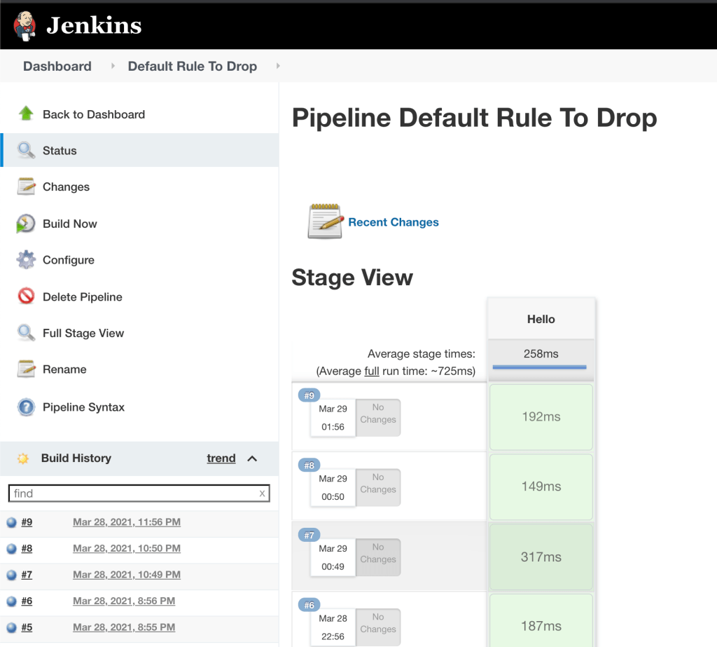
In the Jenkins UI we can see that the pipeline was built several times:
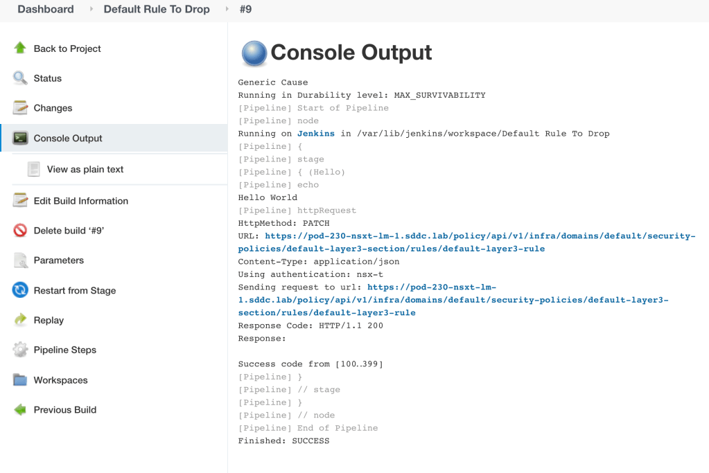
Let’s have a closer look at build #9. The Console Output is pretty useful to have a look at:
Here we can more or less follow what the pipeline script has been doing. In this case things are looking good. Especially the “Response Code: HTTP/1.1 200” which is the NSX-T API’s way of saying it accepted the call and the payload.
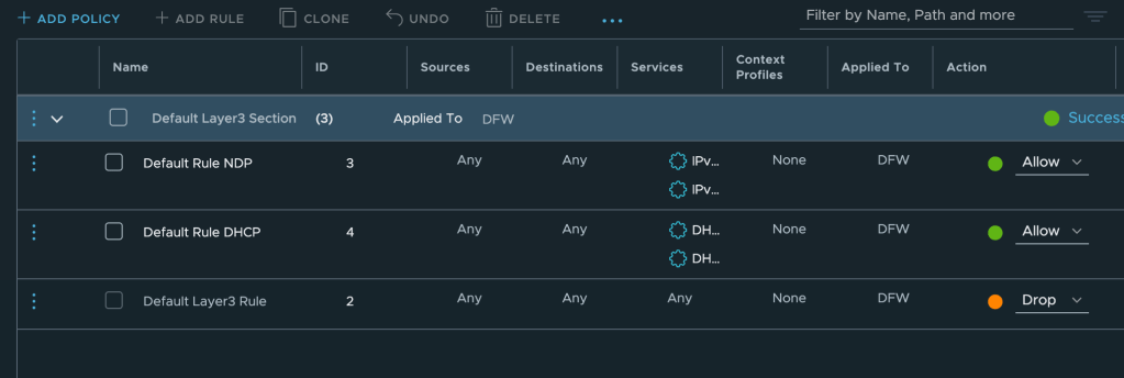
Now let’s have a look at the DFW to see what happened with that firewall rule:
It’s back at dropping traffic. Seems like our event-driven desired state enforcement automation is working!
Summary
Not that difficult, right? We went through setting up a simple event-driven workflow using a Log Insight – Jenkins webhook integration. This example can easily be expanded upon. Both on the Log Insight and the Jenkins side we can of course do much more sophisticated stuff where the only limit is our imagination.
In today’s example the use case was to remediate. It might just as well be to create something. For example when a new tenant’s virtual machine folders are created in vCenter, Jenkins executes an Ansible or terraform script that builds the entire NSX-T logical network infrastructure for that tenant.
One last thing worth mentioning is that the JSON payload send by Log Insight to Jenkins, contains all the event data. This data can be interpreted and used (as variables) in the pipeline script so that we can run very granular/targeted actions.
The NSX-T Central Control Plane (CCP) is building and maintaining a central repository for some tables that make NSX-T the unique network virtualization solution it is. More specifically I’m talking about:
The Global MAC address table
The Global ARP table
In today’s article I’ll have a closer look at these two tables.
MAC Address Table
As soon as a virtual machine’s vNIC is connected to the NSX-T Data Plane, its MAC address as well as the Tunnel End Point (TEP) used to reach that MAC address are registered with the CCP. Now, when the Data Plane receives a frame destined to an unknown MAC address, besides flooding the frame, it will also query the CCP’s MAC address table to see if it can find a matching entry there. The CCP’s MAC address table is also used to pre-populate the local MAC address tables on Transport Nodes before they receive any traffic.
There are two exceptions where MAC addresses of connected vNICs are not registered with the CCP. The first exception is when a vNIC is allowed to send traffic from several source MAC addresses. The second exception is when MAC addresses are learned from an Edge bridge connected to a physical layer 2 network. This is by design and protects the CCP from injection of an arbitrarily large number of MAC addresses into in the network.
So, that’s a pretty cool table, right? One that you might want to have a look at yourself now and then perhaps.
Querying the MAC Address Table
There’s more than one way to retrieve entries from the CCP’s MAC address table. In this article I will show you how it’s done using the Manager CLI. Another option would be to leverage the NSX-T API using curl for example.
We query the MAC address table on a per NSX-T segment basis. To see the learned MAC addresses and their associated TEPs for a segment we first need to know that segment’s Virtual Network Identifier (VNI). From the Manager CLI we run the following command to list segments and their VNIs:
get logical-switches
This gives the following result:
VNI     UUID                                  Name   Type
65542   e1b15ca9-4c04-4692-8926-a4cd769b4776  Web    DEFAULT
65538   0058ae01-04cd-4992-9c2c-60fb764bbad1  App    DEFAULT
In this case we’re interested in the “App” segment which has VNI 65538. We can now run the following command to see the learned MAC address entries for the “App” segment:
As we can see, the table contains two MAC addresses that belong to vNICs connected to the “App” segment. The MAC addresses are reachable via two different TEP IP addresses which are shown in the “VTEP-IP” column.
Each entry also contains a value for the Transport Node ID. This tells us on which transport node the MAC address is connected and basically discloses on which host the virtual machine is running. To translate a Transport Node ID to an ESXi Management IP address we would run:
get transport-node <TransportNode-ID> status
ARP Table
The Central Control Plane also maintains a global ARP table. Thanks to this table we enjoy things like ARP suppression on our NSX-T Data Plane. It’s populated by snooping DHCP and ARP traffic. The snooping itself happens on the individual transport nodes and results are reported back to the CCP.
Querying the ARP Table
Retrieving information from the CCP’s ARP table can be done in different ways as well, but we’ll stick to the Manager CLI today.
As with the MAC address table, querying the ARP table is done on a per segment basis. If we for example would like to see the ARP entries for the “Web” segment, we first need to know that segment’s VNI. In this case we already know that the “Web” segment’s VNI is 65542 and continue by running:
get logical-switch 65542 arp-table
ARP entries are displayed:
VNI     IP          MAC                TransportNode-ID
65542   10.80.1.20  00:50:56:a2:bd:ec  78eeca52-69a8-44f6-a795-f1a1ecc7bdf7
65542   10.80.1.21  00:50:56:a4:b6:e5  4173bca0-4e6e-4ffb-8300-f2f4bed88b29
The two ARP entries showing MAC address and IP address of the connected vNICs. The Transport Node ID is attached as well and can be used to find out on which Transport Node the IP/MAC (virtual machine) is connected.
Modifying Output
With just a couple of entries in these tables, finding relevant information is easy. It becomes a whole different story when hundreds or thousands of virtual machines are connected to a single segment. Luckily we have the option to modify the output:
get logical-switch 65542 arp-table |
   count     Count number of entities
   find      Only show lines that contain regex pattern
   first     Show first N lines of output
   ignore    Ignore lines that contain regex pattern
   json      Show output in JSON format
   last      Show last N lines of output
   more      Show output one page at a time
   sort      Sort command output
To use a very simple example. If we just want to know the number of ARP entries for the “Web” segment that has a 10.80.1.0/24 CIDR, something like this would do the trick:
get logical-switch 65542 arp-table | count 10.80.1.
Output is modified and now looks like this:
Number of lines that match pattern '10.80.1.': 2
Regex patterns are used to filter the command output. Depending on your regex skills (I suck at it) you could construct a pretty advanced query and extract exactly the information that you are looking for.
Summary
In today’s article I went back to some NSX-T basics and looked closer at two important tables that are living within the NSX-T Central Control Plane. The information in these tables is likely available in other systems around your SDDC (vCenter, vROps, vRLI, vRNI, physical network, etc), but personally I think it’s important to know how to extract this information at the source (NSX-T). Sooner or later you will end up in a situation where you depend on that knowledge. 😉
In the last two posts we had a look at two different methods for extending VLANs to NSX-T overlay. In the first post we configured a bridge which works well in scenarios where we the source VLAN and destination NSX-T Edge can achieve layer 2 adjacency. In the second post we configured Layer 2 VPN in a scenario where source and destination environment were completely separate and VLANs could not be stretched.
Both bridging and Layer 2 VPN achieve the same thing from the workload’s perspective: VLAN and overlay segment are one and the same meaning it can roam freely between the two, from a network perspective at least.
Bridging and Layer 2 VPN are technologies native to the NSX-T platform. Apart from some configuration you don’t need additional components to extend a VLAN into overlay. NSX-T, by design, will only provide the network infrastructure for a workload mobility solution. It (luckily) doesn’t interfere with how the workloads are being moved around.
There’s more than one solution out there that can help customers move a workload from A to B. All with their own pros and cons and often positioned for specific use cases like DC pooling, HA, DR, migration, backup, dev/test, staging, etc. One solution that I’ve had a chance to work with in some production environments recently has shown to be exceptionally capable. Not only does it move workloads, it also considers their network connectivity and can handle different migration scenarios with that connectivity in mind.
VMware HCX
VMware HCX is a solution that is primarily used for migrating workloads between environments. Those environments can be data centers or public clouds. The solution consists of a number of services that help customers achieve workload mobility. Naturally, HCX integrates with a number of other VMware solutions and NSX-T happens to be one of them.
The main focus of today’s post will be configuring HCX network extensions between VLANs and the NSX-T overlay. This is just one use case HCX could help you with. Have a look at the HCX product documentation and check out the excellent articles at vMusketeers and HCX.Design if you are interested in learning more about the HCX solution.
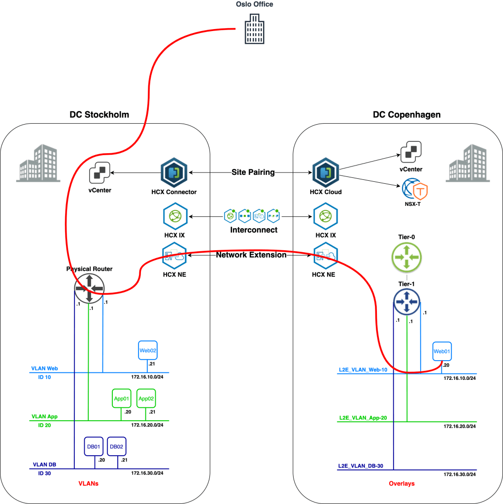
The Scenario
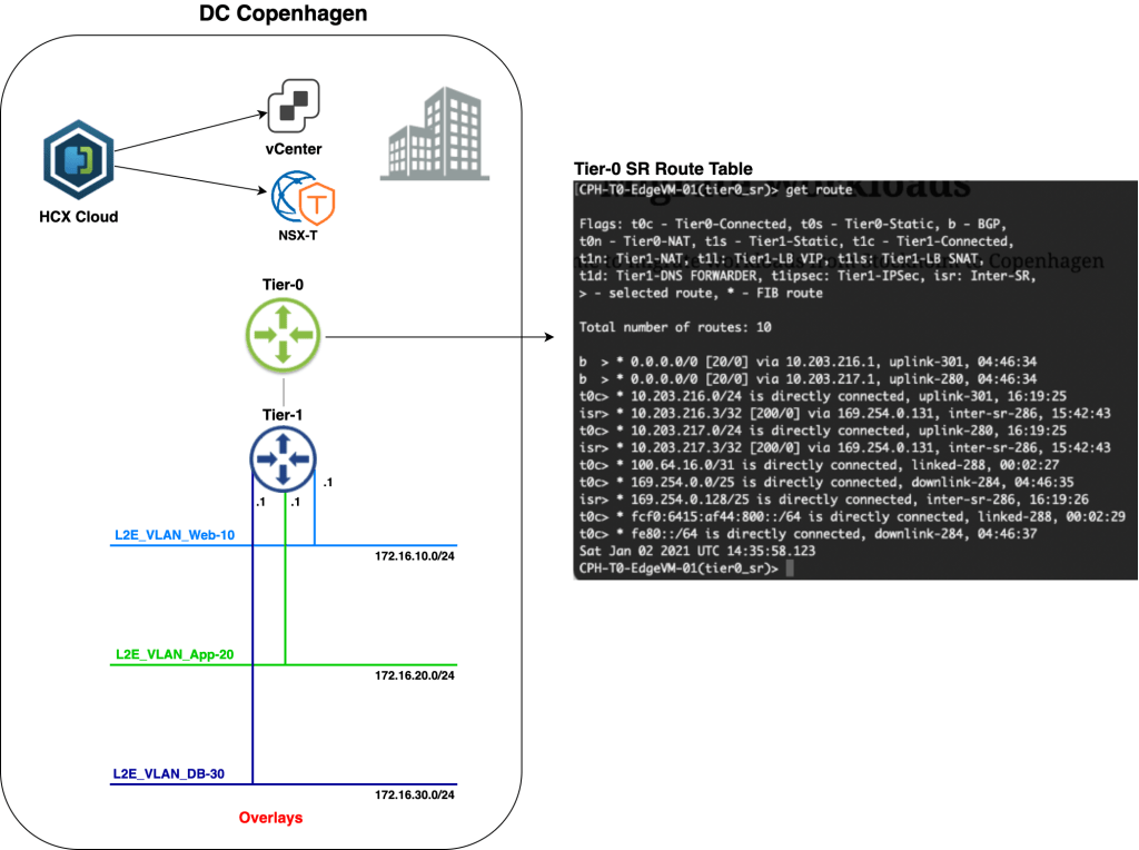
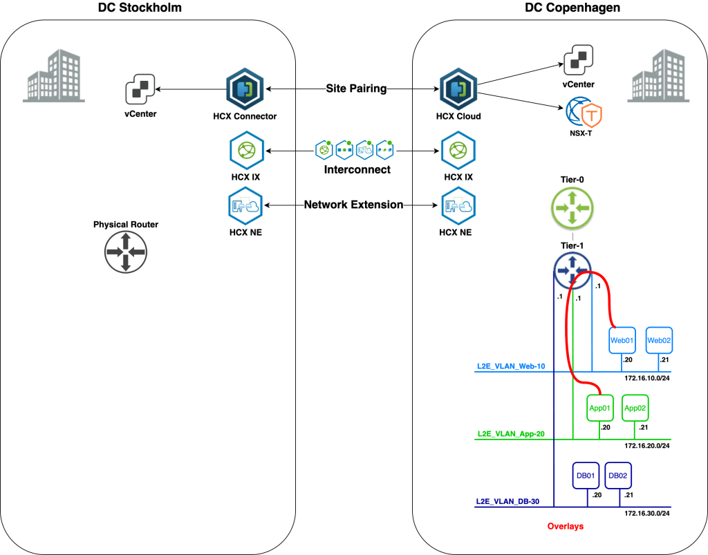
We’ll start with an overview of today’s scenario beginning with a diagram of the environment as it looks right now:
We’re finding ourselves in the middle of a data center re-location project. Virtual machines are to be migrated from a data center in Stockholm to a data center in Copenhagen. The Stockholm DC is running a vSphere-based virtual infrastructure with virtual machines connected to VLANs. The Copenhagen DC is running a fully fledged VMware SDDC and provides NSX-T overlay segments for workload connectivity.
Some preparations were made in advance. NSX-T has been deployed in the Copenhagen DC and a Tier-0 and Tier-1 Gateway are in place. HCX Manager appliances have been installed in both DCs and are connected to their respective vCenter instances and to NSX-T Manager in Copenhagen. A HCX Site Pairing has been created between the DCs:
When it comes to the actual workload migration, we are told that downtime is not an option. We won’t have access to the guest OS of the workloads, so no fiddling around in there. Using HCX, as the customer points out, we should be able to carry out this type of migration without problems. After all, the sales guy told them it would all “work like a dream”.
It’s now up to us to make the dream come true. We need to configure the HCX network extensions and carry out seamless migration of the virtual machines from Stockholm to Copenhagen. We’re looking at a 5-step process:
That’s a lot of work so we better get started right away!
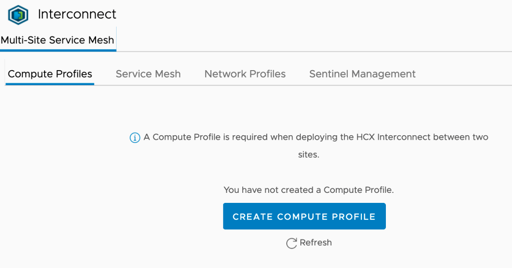
Step 1 – Configure HCX Interconnect
As the HCX Site Pairing is already in place, we can start with configuring the HCX Interconnect. Setting up a HCX Interconnect consists of configuring the following items:
Network Profiles
Compute Profiles
Service Mesh
Network Profiles
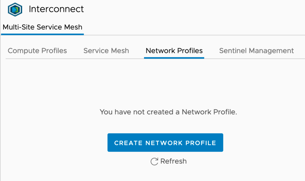
For our particular scenario we’ll create two network profiles within each site’s HCX Interconnect: One for Management and one for vMotion. In the HCX Manager UI we navigate to Infrastructure > Interconnect > Network Profiles. Click the Create Network Profile button:
The Management Network Profile for Stockholm looks as follows:
Most of the configuration details of this network profile will be self-explanatory. Notice that the Management IP pool contains two available IP addresses which is the required number for this scenario: One management IP address for the IX (Interconnect) appliance and one for the NE (Network Extension) appliance:
The vMotion Network Profile for Stockholm looks like this:
One IP address for vMotion is sufficient. We adjust the MTU to the maximum size supported by the physical network (9000 bytes in this case).
Both network profiles are now in place in Stockholm:
We create similar HCX Network Profiles in Copenhagen. The process is identical apart from different IP addresses.
Compute Profiles
Next up are the HCX Compute Profiles. Compute profiles contain the compute, storage, and network settings that HCX will use on a site to deploy the Interconnect appliance. In the HCX Manager UI we navigate to Infrastructure > Interconnect > Compute Profiles. Click the Create Compute Profile button:
A guided process helps us configure and create the compute profile. Let’s walk through the configuration for the Copenhagen compute profile
1. Name your Compute Profile
Giving it a descriptive name so that everybody understands what we’re talking about:
2. Select Services to be enabled
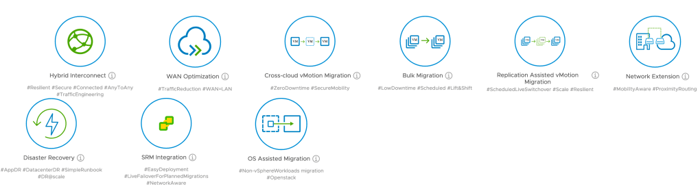
Here we select the HCX services that we want to enable in this compute profile. For our scenario we enable:
Hybrid Interconnect
Cross-cloud vMotion Migration
Replication Assisted vMotion Migration
Network Extension:
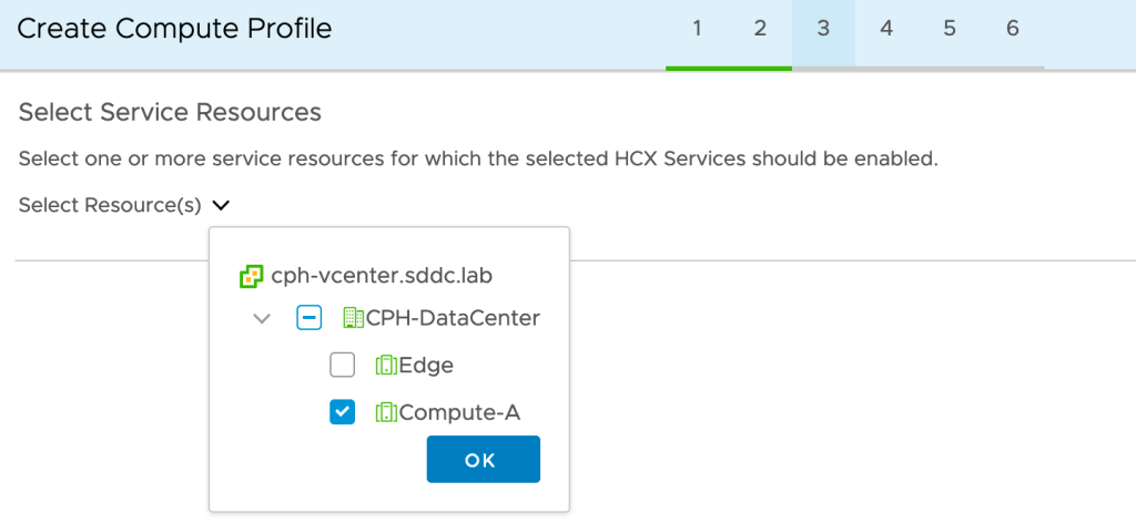
3a. Select Service Resources
We select the destination compute cluster where the migrated workloads should end up. This is a vSphere cluster called Compute-A in our destination environment:
3b. Select Deployment Resources and Reservations
In Copenhagen we want to deploy the IX and NE appliances in a separate vSphere cluster called Edge. We also need to select a datastore and can optionally choose a vCenter VM folder. We leave the reservation settings untouched.
4a. Select Management Network Profile
At this step we select the Management Network Profile that we created earlier on:
4b. Select Uplink Network Profile
In our scenario the management network will be used to reach the HCX appliances at the other site. We select the Management Network Profile as the Uplink Network Profile.
4c. Select vMotion Network Profile
At this step we select the vMotion Network Profile that we created earlier on:
4d. Select vSphere Replication Network Profile
We select our Management Network Profile as the vSphere Replication Network Profile:
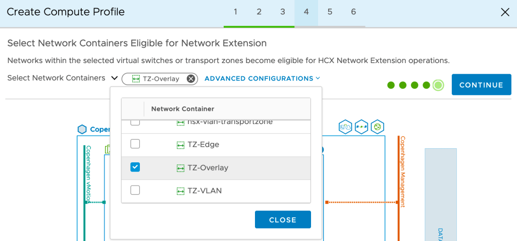
4e. Select Network Containers Eligible for Network Extension
It’s critical that we get this one right for our project. To be able to extend to overlay segments later on, we must select the NSX-T overlay transport zone here. In our case that transport zone is called TZ-Overlay:
5. Review Connection Rules
At this step we can view and copy the connections rules that HCX will created as part of the compute profile. This is particularly important information if there are firewalls between any of the different networks where HCX will have one or more endpoints.
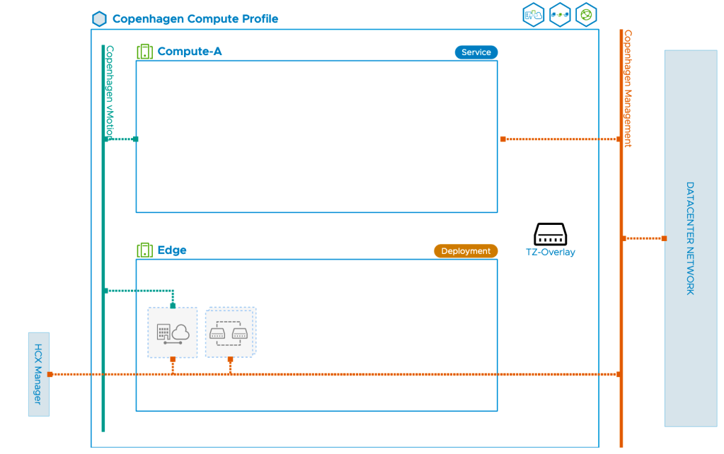
6. Ready to Complete
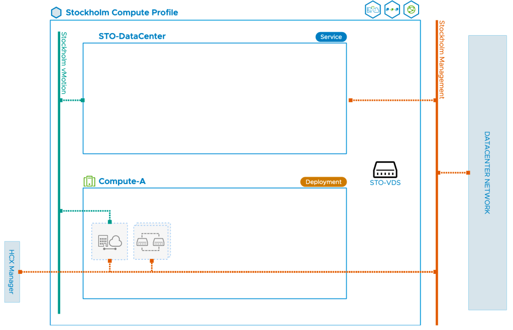
At the final step we’ll have a look at the diagram that gives us a nice overview of the compute profile and its components:
Once the compute profile in Copenhagen is created we create a similar compute profile in Stockholm. The key difference between the Copenhagen and Stockholm profiles is that in Stockholm we select the VDS for network extension. The compute profile diagram for Stockholm looks like this:
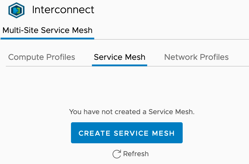
Service Mesh
The last step of configuring the HCX Interconnect is to create the Service Mesh. This is initiated from the Stockholm HCX Manager where we navigate to Infrastructure > Interconnect > Service Mesh. Click in the Create Service Mesh button:
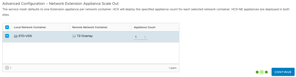
A guided process will help us get the service mesh up and running. It’s a very straight forward process. One thing to note is that we have the option to increase the number of Network Extension appliances to be deployed as part of the Service Mesh. For our exercise one appliance will do, but it’s good to know we can scale out if necessary.
At the last step of the wizard we configure a name for the service mesh and can view another diagram showing the topology of the service mesh we’re about to deploy:
Once the service mesh is created we can see its status and properties in the HCX Manager UI:
Everything green and happy so we’ll move on.
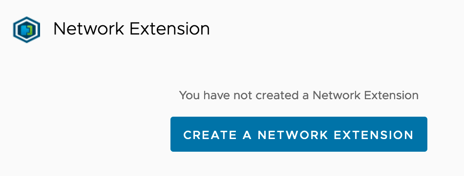
Step 2 – Create HCX Network Extension
With the HCX Interconnect now fully configured and deployed we start creating the HCX Network Extensions needed for our project. Within the HCX Manager interface in Stockholm we navigate to Services > Network Extension. Click Create a Network Extension:
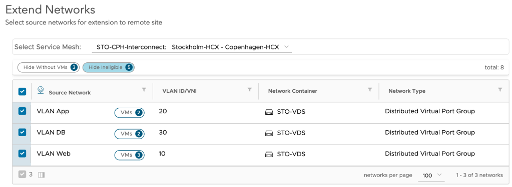
We are presented with a list of distributed port groups that are eligible for the network extension:
We select Stockholm’s three distributed port groups and click Next. Now things start to get interesting:
Here we basically configure the NSX-T side of the extension. We select the Tier-1 Gateway and configure a gateway IP address for the overlay segments. Note that HCX Network Extension is going to create these overlay segments for us.
Once we click Submit the network extension is created. After a minute or so we should see the following status:
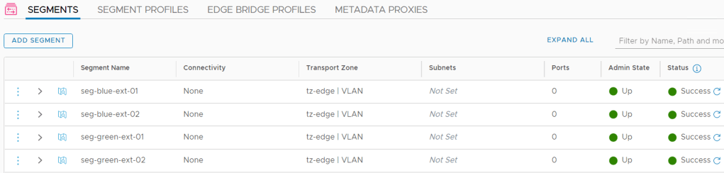
So what do things look like within NSX-T in Copenhagen at this point?
Pretty much what we were hoping for (apart from the horrible segment names). HCX Network Extension has created three overlay segments connected to the Tier-1 Gateway; one for each extended distributed port group in Stockholm. We also see that the HCX network extension virtual appliance has connected itself to the segments.
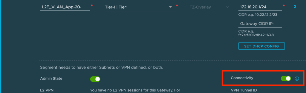
A closer look at one of the created overlay segments reveals that connectivity is currently switched off.
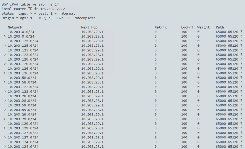
This means that the IP subnets associated with those overlay segments are currently not advertised to any routing table. If we for example look at the routing table of Copenhagen’s Tier-0 Gateway we indeed see that it doesn’t contain routes to any of the new overlay segments (172.16.x.x):
This is by design, of course. At this point the Tier-1 Gateway is not participating in any routing as we’re effectively bridging back and forward between the data centers. More on this in a moment.
Step 3 – Migrate Workloads
Finally, time to move workloads from Stockholm to Copenhagen. Migrations are managed in the HCX Manager UI under Services > Migration. Click on Migrate to kick off the migration wizard:
We’ll start with migrating virtual machine Web01. We need to specify some details for compute and storage at the destination. As Web01 is connected to a HCX extended distributed port group, it (correctly) assumes that we want to connect the virtual machine to the corresponding overlay segment once it lands in Copenhagen:
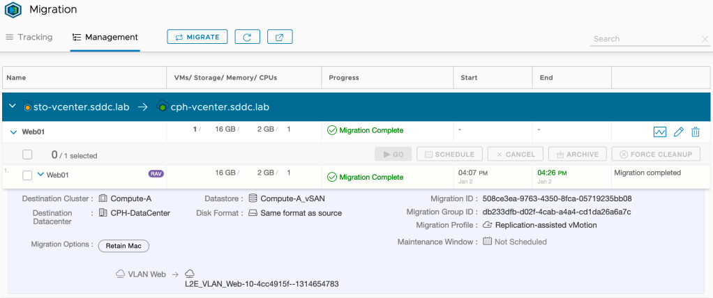
Pressing Go starts the workload migration. Once Replication Assisted vMotion (RAV) is done with its migration magic, we’ll have the following status in the HCX Manager UI:
“Migration Complete”. That’s a good start I think. Let’s have a look in Copenhagen’s vCenter:
Yup, virtual machine Web01 is definitely running in Copenhagen. What do we see from an NSX-T point of view?
A virtual interface with a familiar IP address. Looking good there as well!
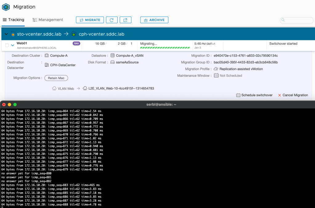
Seamless?
So exactly how seamless is a migration like this? This will depend on a number of things of course, but when using HCX vMotion/Replication Assisted vMotion and HCX network extension it could indeed be very close to seamless. I ran a ping during the migration of Web01 and I missed just 3 replies:
I think for most customers and scenarios this would be good enough.
Step 4 – Validate Connectivity
So, the Web01 virtual machine was migrated successfully to the Copenhagen data center. We need to have a look at its network connectivity. Before we do that, let’s check the diagram for the current situation:
A couple of things changed. We now have a fully configured HCX Interconnect and a HCX Network Extension connection. HCX NE created the required NSX-T overlay segments in Copenhagen. Virtual machine Web01 now lives in Copenhagen and is connected to an overlay segment. All looking good I believe.
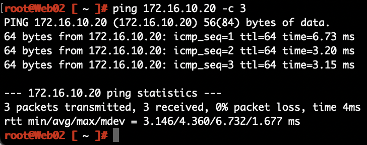
Can we ping it?
From Web02 in Stockholm to Web01 in Copenhagen:
The network path for the packets:
From Web01 in Copenhagen to DB01 in Stockholm:
The network path for those packets:
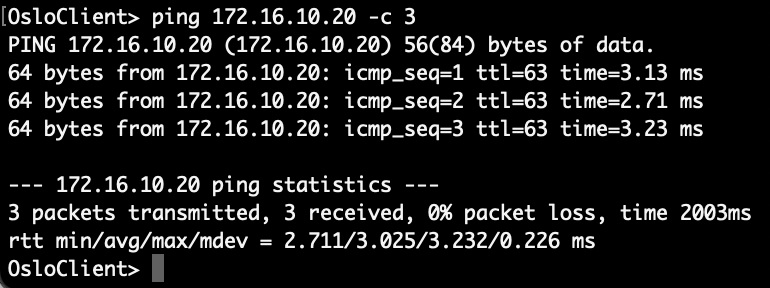
From a client in the Oslo office to Web01 in Copenhagen:
The packets from Norway to Denmark:
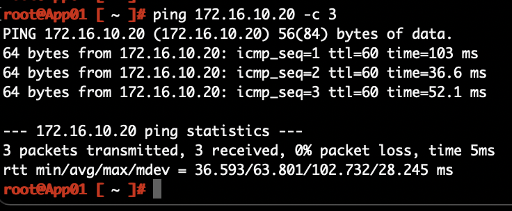
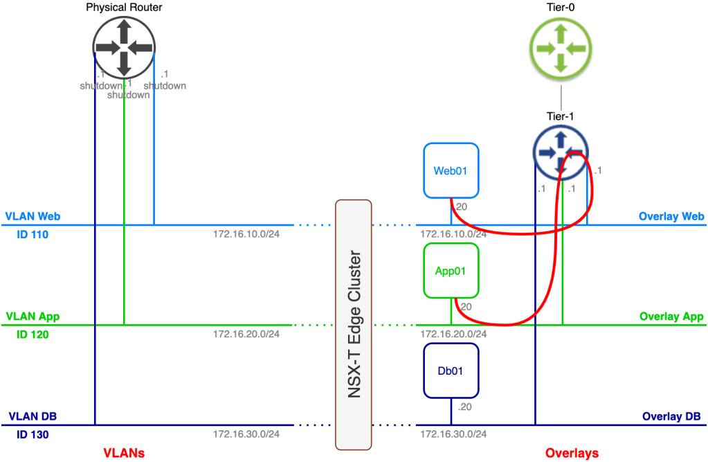
That all works as expected, but as you probably noticed, all routing is still done in the Stockholm DC. This becomes painfully obvious after migrating App01.
A ping from App01 in Copenhagen to Web01 in Copenhagen:
The network path:
Look at the size of that thing! This phenomenon is called traffic tromboning. It’s something you easily end up with when messing around with bridging and routing over data center interconnects. You normally don’t want these type of network paths to stick around for too long. We’re moving workloads here which means this should be a temporary situation. When we unextend the networks, we’ll also make sure that routing takes place on the Tier-1 Gateway in Copenhagen.
Avoid Trombones?
When using HCX Network Extension to extend networks from a data center environment to a VMware Cloud on AWS SDDC environment, you have the option to enable HCX Mobility Optimized Networking. MON provides routing based on the locality of the source and destination virtual machines. The MON feature hasn’t made its way to HCX Network Extension between data centers yet, but is available for early adoption and can be requested from VMware. This might be something to consider if your network extensions are going to be around for a longer period of time.
Step 5 – Unextend Networks
We’ve successfully migrated all workloads from Stockholm to Copenhagen. Connectivity is good, but it’s really time to get rid of those traffic trombones. Two important things to keep in mind before unextending a network:
The extended network at the source (VLAN in Stockholm in our scenario) should be vacated and ready to be shut down.
Enable connectivity on the overlay segment at the destination (Copenhagen in our scenario).
Unextending a HCX extended network is simple and done from the HCX Manager UI under Services > Network Extension. Here we click the three vertically aligned dots and chose Unextend Network:
As mentioned, once the network is unextended we need to shut down the VLAN IP interface in Stockholm and enable connectivity on the overlay segment in Copenhagen.
From now on the Tier-1 Gateway will handle routing traffic for this segment. We repeat the unextend process for the other extended networks and after that we’re enjoying an optimal network traffic path:
From Web01 in Copenhagen to App01 in Copenhagen:
An optimized network path:
In real life we would probably want to automate the whole unextending process including shutting down VLANs and enabling segment connectivity to keep the impact to a minimum.
Mission Completed
Seamless migration of workloads from Stockholm to Copenhagen and from VLAN to NSX-T overlay. We did it!
Yes, I renamed the overlay segments to something more user friendly 😉
Summary
Quite a battle, but it was worth it, right?
In this post we walked through setting up HCX network extensions between VLANs in one data center and overlay segments in another. This is yet another way to migrate workloads to NSX-T overlay without downtime. So, what does HCX bring to the table that the NSX-T native network extension methods do not? Well, if you read this post I think it’s quite obvious. HCX takes care of all aspects surrounding workload migrations. Not only does it handle bridging of networks between different environments, it also orchestrates and carries out the migrations in an intelligent way.
In the previous article we had a look at how VLAN-connected workloads were migrated to NSX-T overlay by setting up a bridge between VLANs and NSX-T overlay segments. This works well in scenarios where layer 2 adjacency between source and destination environment can be achieved. In other words, we can stretch the source VLAN(s) to the NSX-T Edge where the bridging takes place.
When source and destination environments are in completely separate environments, stretching VLANs might not be an option and thus bridging is off the table. But you still have all these workloads that need to be migrated to NSX-T overlay without re-IP and with minimum service disruption. So now what?
In this article we’re going to have a look at another method to facilitate migration of workloads from VLAN to NSX-T overlay when source and destination environment are different data centers and different administrative entities. By leveraging layer-2 VPN a customer will migrate their VLAN-connected application to a service provider’s NSX-T overlay. We have a lot to do so no time to waste!
The Environment
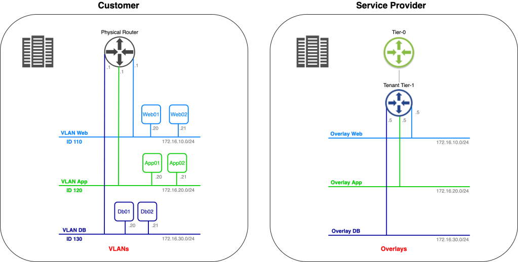
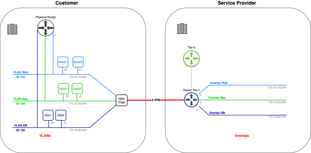
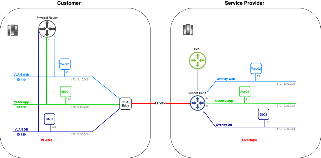
Let’s begin with a look at the starting point for today’s exercise:
We have the customer environment on the left. One of their applications, consisting of six virtual machines, connected to three different VLANs, is to be migrated to the service provider on the right. The service provider has already prepared a spot for the customer’s application in their software-defined network.
We’re assisting the customer and service provider with phase one of the application migration. This phase consists of migrating Web02, App02, and Db02 to the service provider’s environment. IP addresses of the virtual machines must remain the same throughout the migration and inter/intra application tier communication must stay intact regardless of where a virtual machine is running (customer or service provide environment).
Mission impossible? Let’s find out!
Step 1 – Create Port Groups (Customer side)
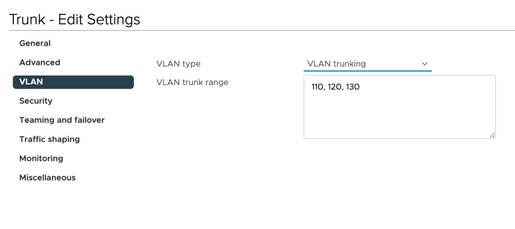
As a preparation for the next steps, we begin with creating two distributed port groups in the customer’s vSphere environment: One trunking port group and one “uplink” port group.
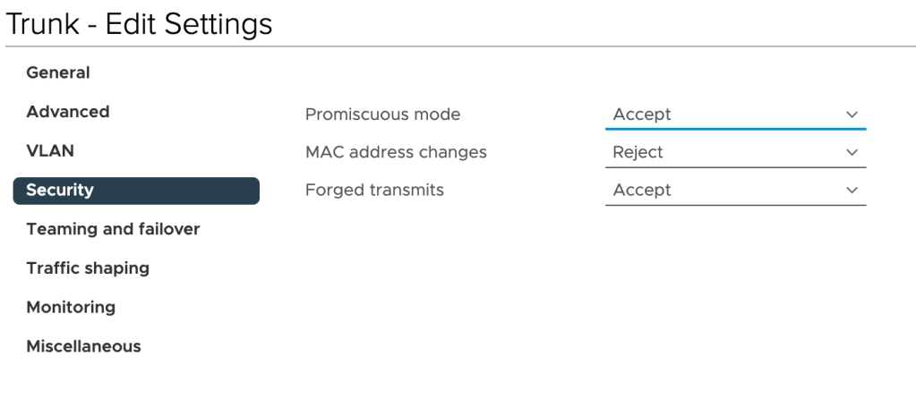
The “Trunk” port group is configured to carry VLANs 110 (Web), 120 (App), and 130 (DB):
Furthermore, we need to enable Promiscuous mode and Forged transmits on this port group by setting these to Accept:
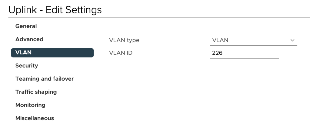
The “Uplink” port group should be mapped to a VLAN that can route traffic to the service provider’s L2 VPN endpoint. In our scenario the customer has allocated VLAN 226 for the purpose:
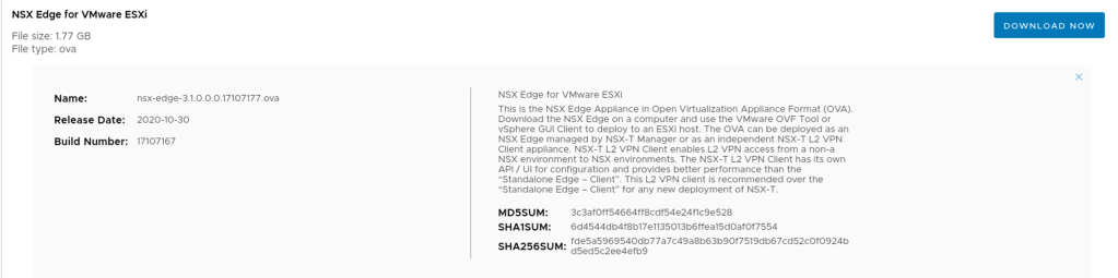
Strange enough, our customer has not implemented NSX-T in their environment. Fortunately, we can deploy a standalone NSX Edge appliance that will act as the L2 VPN client. This standalone NSX Edge appliance can be downloaded as an OVA package from VMware:
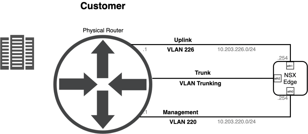
Before deploying the appliance let’s have a quick look at a diagram showing how this thing is connected to the network:
Things easily get a bit confusing during the OVA deployment so I’ve summarized the network settings for the Edge appliance OVA deployment in the table below:
OVF Template Name
Port Group
Edge UI Name
IP Address
Network 0
Management
Management (eth0)
10.203.220.254/24
Network 1
Uplink
eth1
10.203.226.254/24
Network 2
Trunk
eth2
–
Network 3
– (HA, not used here)
eth3
–
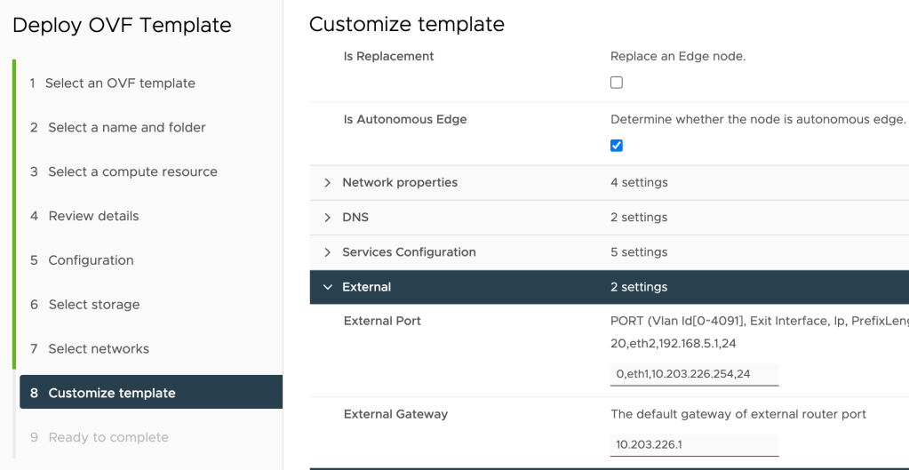
The following settings are configured at the “Customize template” step during the appliance OVA deployment:
Setting
Value
Is Autonomous Edge
Yes
External Port
0,eth1,10.203.226.254,24
External Gateway
10.203.226.1
The “0,eth1,10.203.226.254,24” string instructs the installation to configure “10.203.226.254/24” as the IP address on “eth1” (the uplink interface). The “0” indicates that the interface is connected to a port group that has a VLAN ID specified. If it were connected to a trunking port group we would have to specify the VLAN ID here instead.
The settings from the table above configured during the OVA deployment:
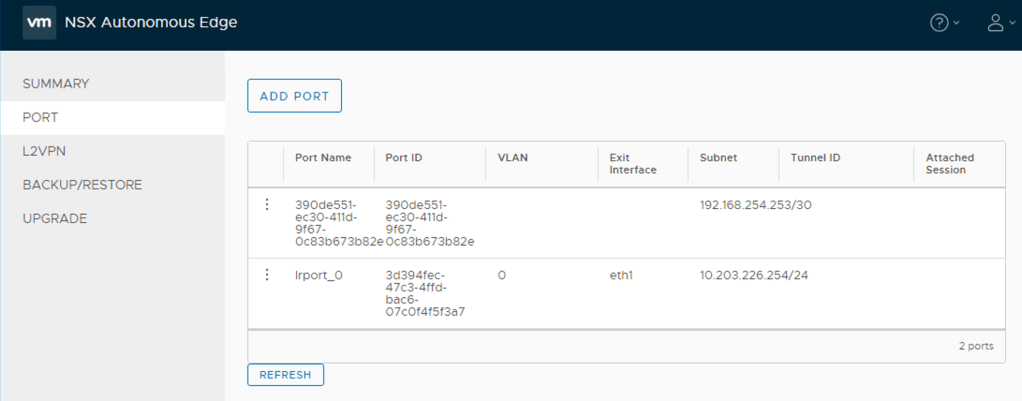
Once the NSX Edge appliance has been deployed we can navigate to the NSX Edge appliance UI on the configured management FQDN/IP address:
We’ll come back to the customer’s NSX Autonomous Edge in a bit.
Step 2 – Configure VPN Service (Service Provider side)
At the service provider side we need to configure a L2 VPN Server Session. This is achieved by completing a couple of steps which I’ll walk through here.
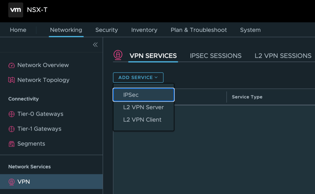
Add IPSec Service
First we need to add an IPSec Service, which is the underlying protocol for the L2 VPN connection. IPSec services can be managed from the NSX Manager UI under Networking > Network Services > VPN. Here we click on Add Service > IPSec:
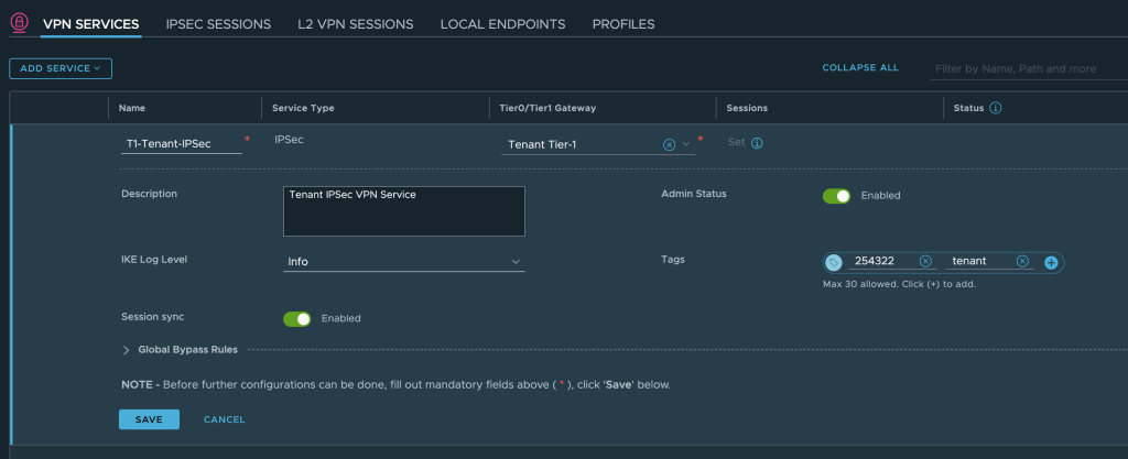
We enter a name, select the customer’s Tier-1 Gateway (which was already created), and save the configuration:
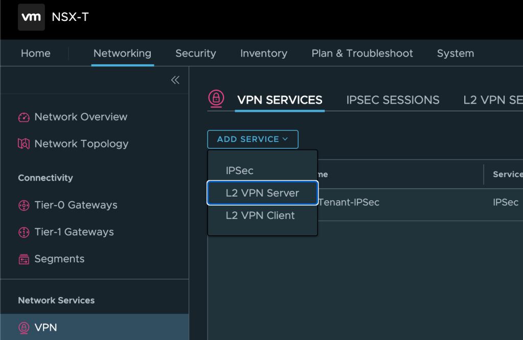
Add L2 VPN Server
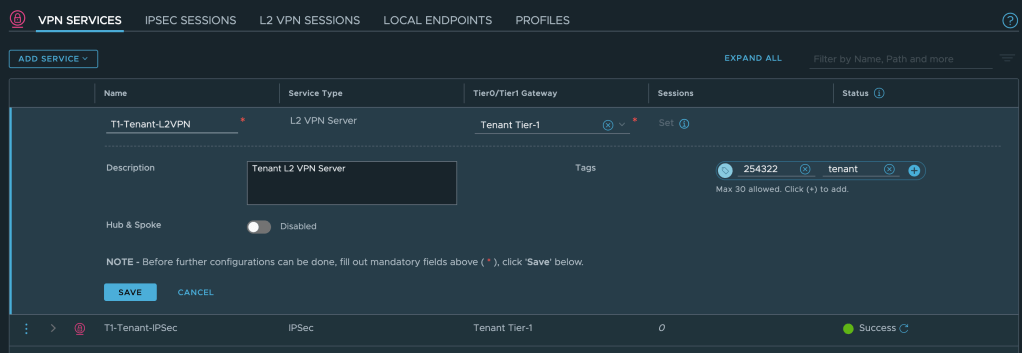
Next we need to add an L2 VPN Server. We click on Add Service > L2 VPN Server:
Enter a name, select the customer’s Tier-1 Gateway, and save the configuration:
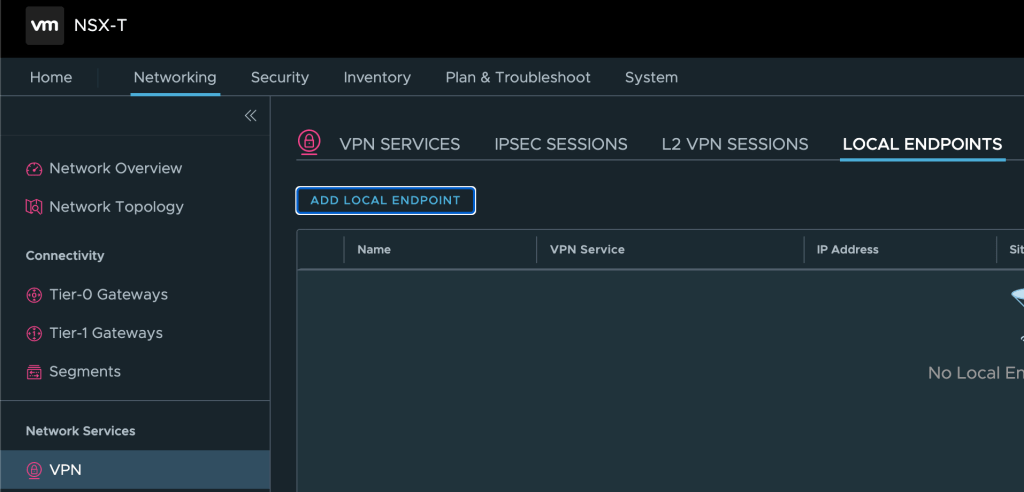
Configure VPN Endpoint
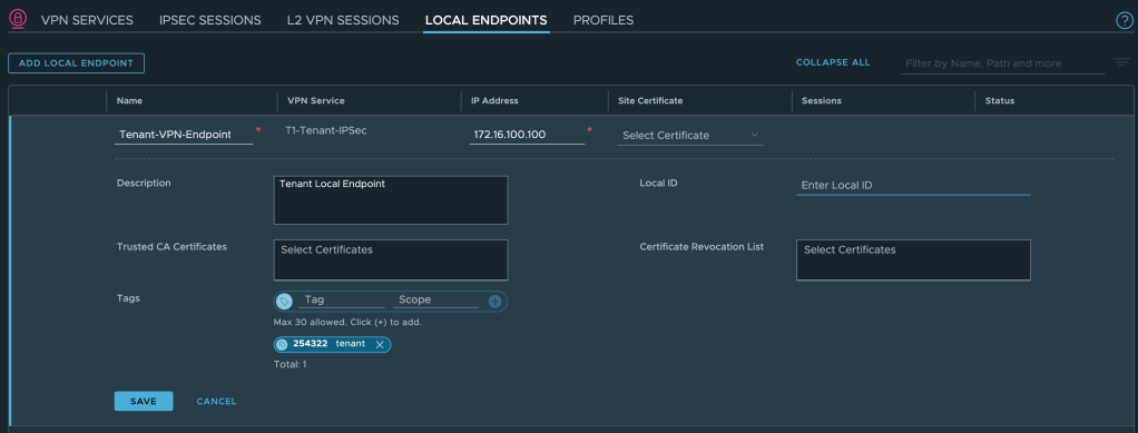
A local VPN endpoint is required and must be advertised throughout the network. Click on Local Endpoints > Add Local Endpoint:
Enter a name, select the IPSec VPN service we just created, enter a valid IPv4 IP address, and save the configuration:
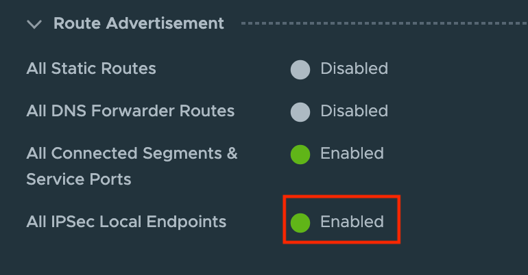
To advertise this local VPN endpoint throughout the network, we enable a Route Advertisement on the customer’s Tier-1 Gateway:
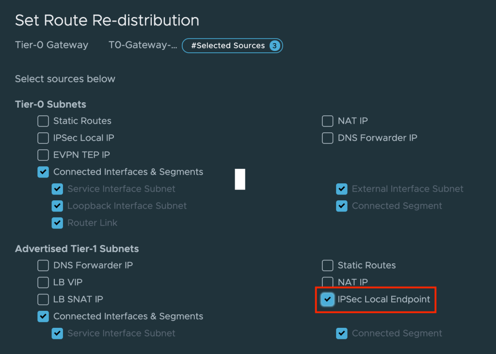
On the service provider’s Tier-0 Gateway we enable re-distribution of Tier-1 Gateway IPSec Local Endpoints:
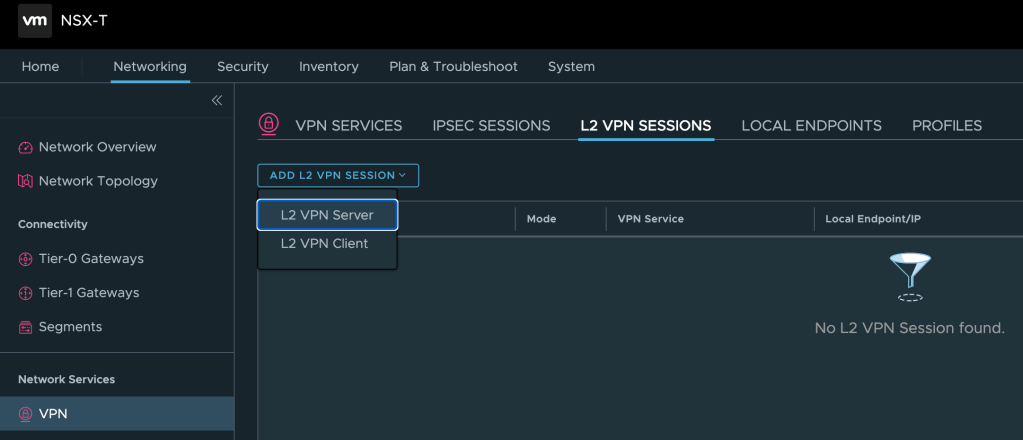
Configure L2VPN Server Session
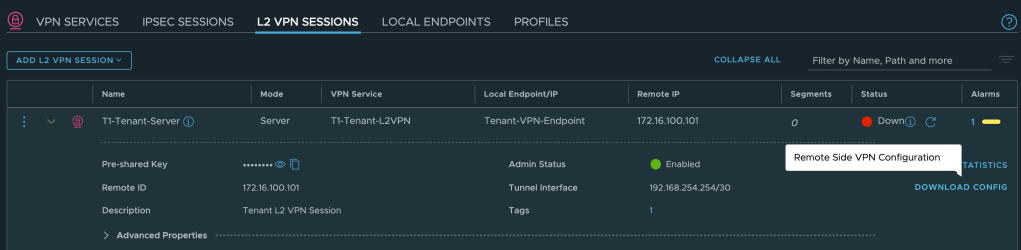
We can now configure the L2 VPN Server Session itself. L2 VPN Server sessions are managed under L2 VPN Sessions. Click on Add L2 VPN Session > L2 VPN Server:
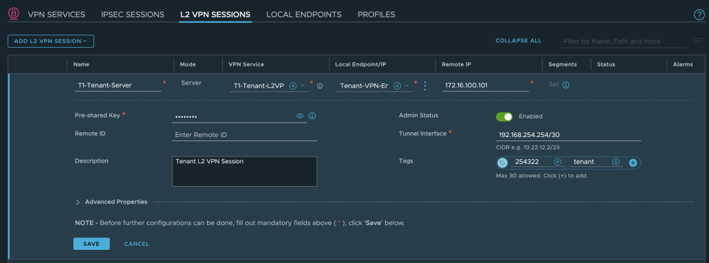
We enter a name, select the L2 VPN service, and the local endpoint. We must also specify the remote IP address which is the IP address that we configured on the uplink interface of the customer’s NSX Autonomous Edge (10.203.226.254). A valid CIDR for the tunnel interface is required as well:
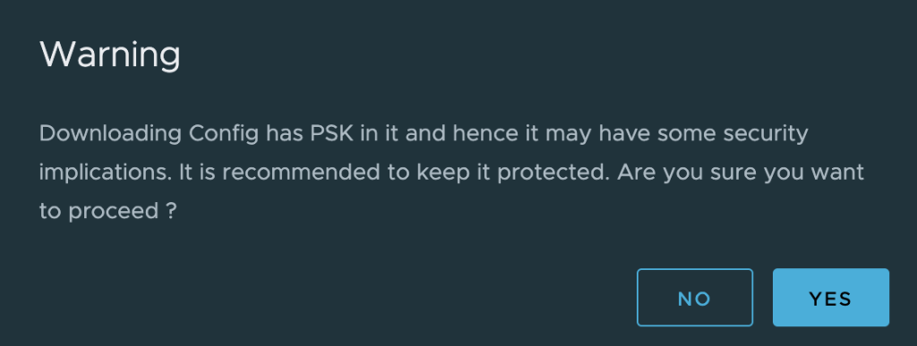
Once the L2 VPN session has been saved we can download the remote side VPN configuration which is needed on the NSX Autonomous Edge in the customer environment:
Save the configuration file to your workstation somewhere:
Step 3 – Configure L2 VPN Client (Customer side)
Now that the service provider has prepared the customer’s Tier-1 Gateway we head over to the customer environment and their NSX Autonomous Edge.
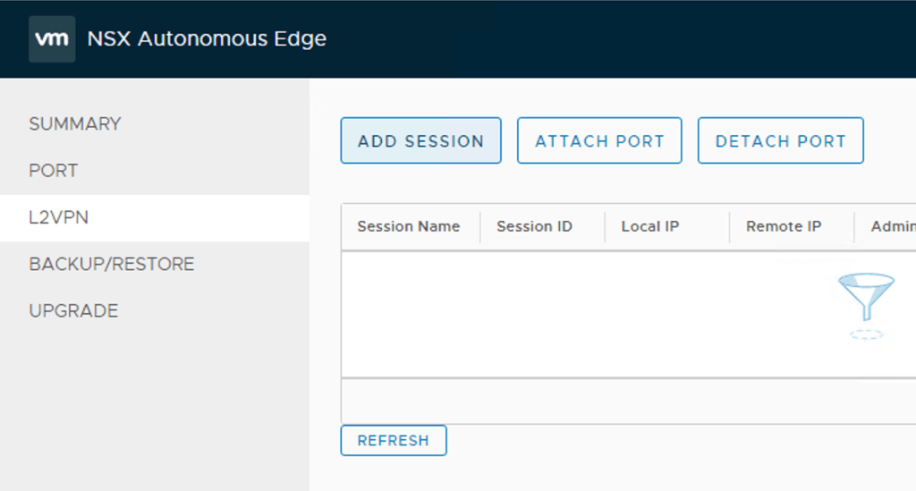
Add L2 VPN Session
After logging in to the NSX Autonomous Edge UI we click L2VPN > Add Session
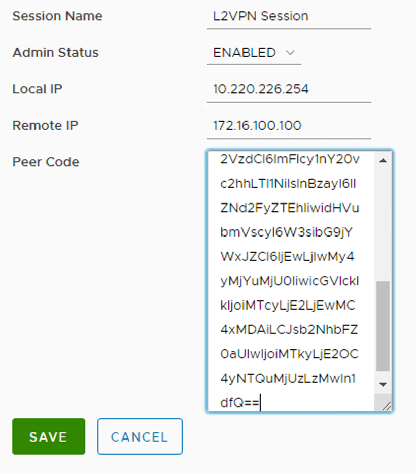
We enter the following details for the L2 VPN session:
Setting
Value
Session Name
L2VPN Session
Admin Status
Enabled
Local IP
10.203.226.254
Remote IP
172.16.100.100
Peer Code
Peer code from the VPN configuration file
The settings as seen in the UI:
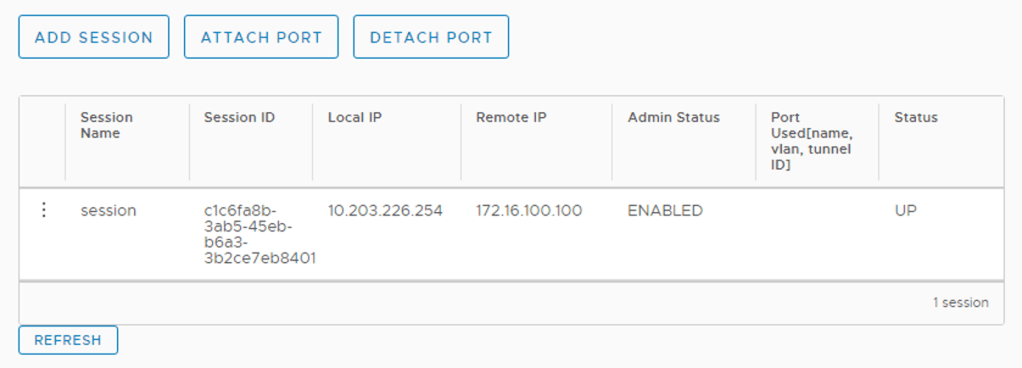
After saving the session configuration we should see the L2 VPN session with a “Up” status.
Extend VLANs
Time to extend the customer’s VLANs into the L2 VPN tunnel. In the NSX Autonomous Edge UI click on Port > Add Port
We enter the following details for each of the VLAN extensions:
Setting
VLAN 110
VLAN 120
VLAN 130
Port Name
VLAN110
VLAN120
VLAN130
Subnet
–
–
–
VLAN
110
120
130
Exit Interface
eth2
eth2
eth2
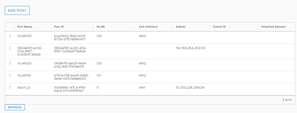
The NSX Edge UI once the ports have been added:
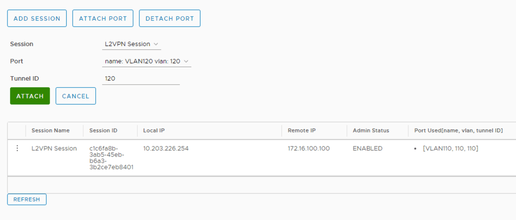
The last step is to attach these ports to the L2 VPN session. Click L2VPN > Attach Port. We select the session, the port, and configure a Tunnel ID that matches the VLAN ID. Click Save.
We’ve now effectively extended these VLANs over the L2 VPN tunnel.
Now that the customer’s VLANs have been extended we need to do the same for the overlay segments over at the service provider.
In the NSX Manager UI navigate to Networking > Connectivity > Segments. Modify each of the customer’s segments as follows:
Setting
Overlay Web
Overlay App
Overlay DB
L2 VPN
T1-Tenant-Server
T1-Tenant-Server
T1-Tenant-Server
VPN Tunnel ID
110
120
130
The settings for the “Overlay Web” segment
Step 5 – Test Connectivity
Now is a good time to check if all our hard work has actually resulted in something. Let’s first have a look at an updated diagram of the environment to see where we stand from a logical point of view:
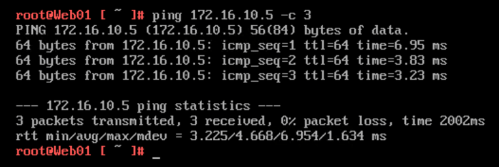
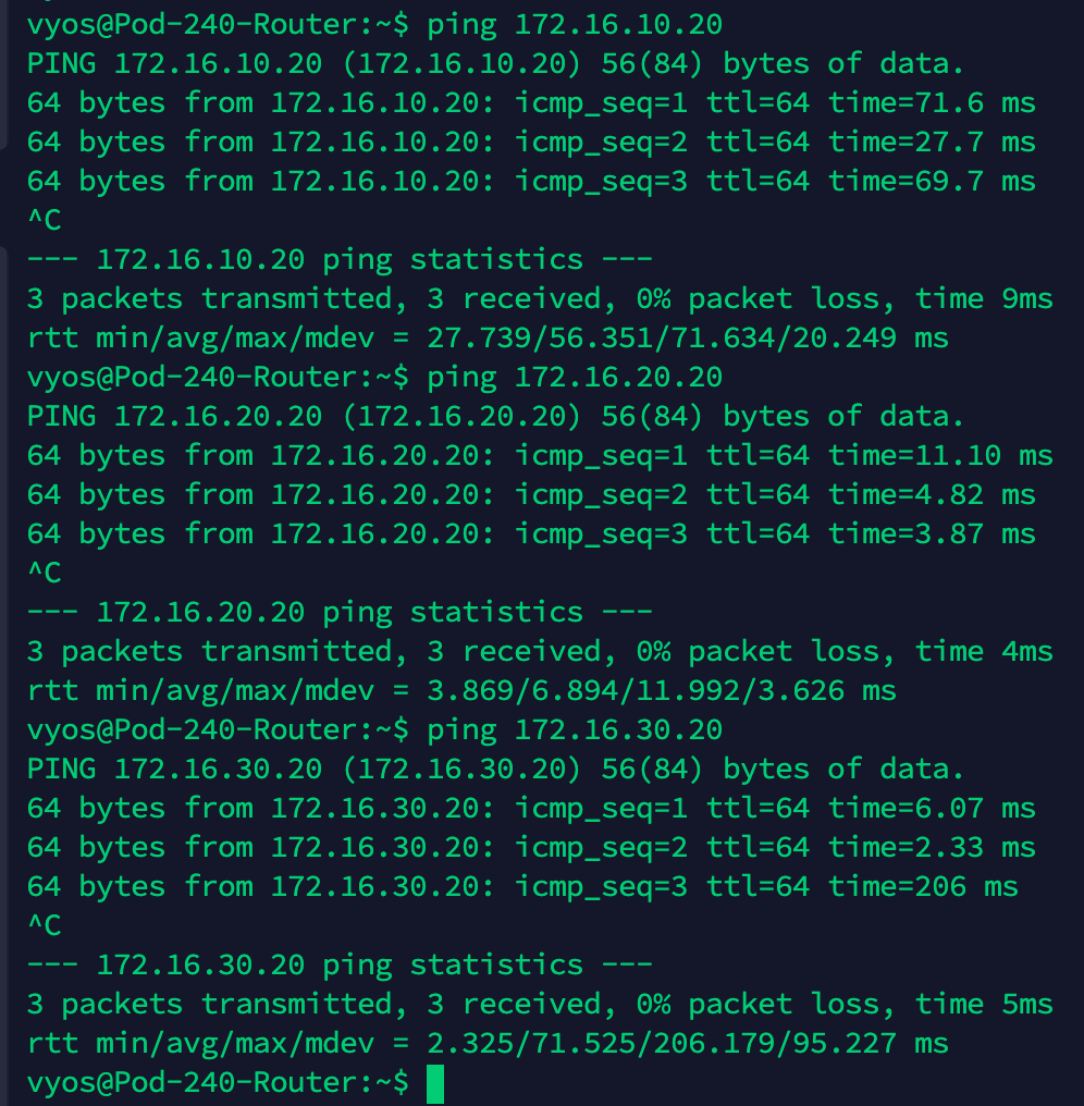
All that hard work for just a tiny red line!? Ok, let’s do a simple ping test from Web01 (172.16.10.20) to the Tier-1 Gateway downlink interface for “Overlay Web” (172.16.10.5):
It works!
Step 6 – Workload Migration
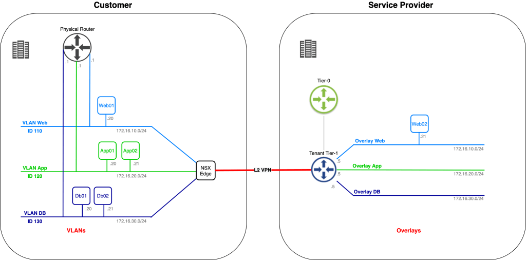
The time has come to stretch apart the customer’s application. “Web02” is migrated to the service provider environment while “Web01” is staying behind in the customer’s environment (for now).
The workload migration itself can be done in a number of ways (OVF export/import worked pretty well in my lab ;-). But let’s assume that this has been taken care of and that we’re now finding ourselves in the following situation:
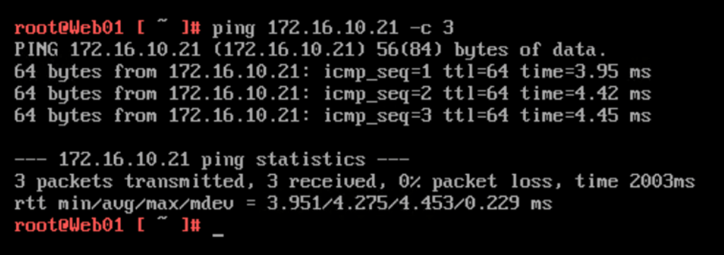
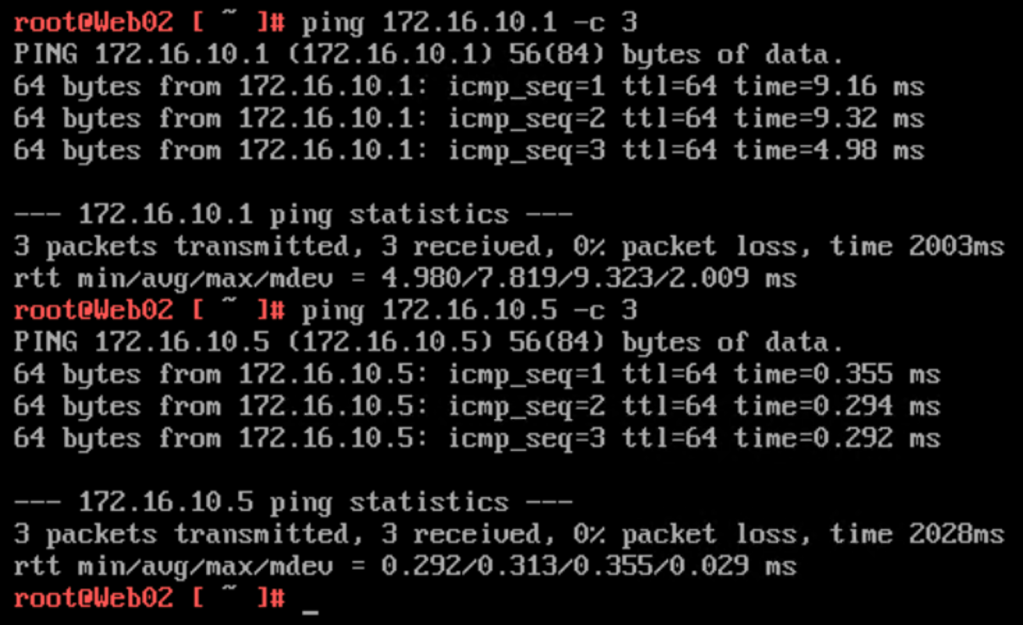
Let’s have a look at the connectivity by running a ping from “Web01” (172.16.10.20) in the customer’s environment to “Web02” (172.16.10.21) in the service provider’s environment.
Works like charm! Pinging the VLAN 110 interface (172.16.10.1) and the Tier-1 Overlay Web downlink interface (172.16.10.5) from “Web02” (172.16.10.21):
Only the difference in RTT reveals that there’s something going on between these two IP addresses. Something like a L2 VPN connection 😉
After this initial success, the customer decided to migrate “App02” to the service provider as well:
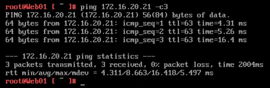
With 33% of the application now on the service provider side, we better make sure that inter-tier connectivity is still working. A ping from “Web01” (172.16.10.20) to “App02” (172.16.20.21):
No issues here.
Things going better than expected, the customer wants to complete phase one of the migration project and migrates “Db02” to the service provider as well:
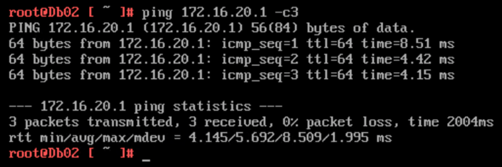
Pinging the VLAN 120 interface (172.16.20.1) in the customer environment from the newly migrated “Db02” (172.16.30.21) virtual machine:
Phase one completed!
Once phase two is completed, we would un-extend the VLANs and change IP address on the customer’s Tier-1 Gateway downlink interfaces from .5 to .1. All workloads migrated without touching their OS.
Summary
In this article we had a look at how to migrate VLAN-connected workloads to an NSX overlay located in a completely separate environment. In a scenario like this, where bridging is not an option, we leverage L2 VPN to extend VLANs to NSX-T overlay.
Hopefully you found reading this post worth your time. Thank you!
Organizations implementing NSX-T overlay have several options when it comes to migrating existing VLAN-connected workloads to NSX-T overlay segments.
Common methods include re-IP’ing or re-deploying workloads to a new IP space allocated to NSX-T logical networking. It gives the workload somewhat of a fresh start. Besides, a re-IP process can be a very useful exercise eliminating those (hardcoded) IP address dependencies within an application.
There are however situations where neither re-IP nor re-deploy are alternatives. The reasons for this will vary, but it often has something to do with time, complexity, and cost. In those situations the workload will have to be migrated as is. Is this possible? How is it done?
In today’s article I’m going to walk through setting up a bridge between some VLANs and NSX-T overlay segments. It’s this NSX-T construct that makes it possible to migrate workloads from VLANs to overlay without having to make any changes to the workloads themselves. Let’s get started!
The Environment
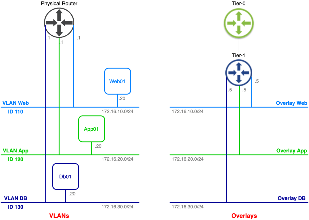
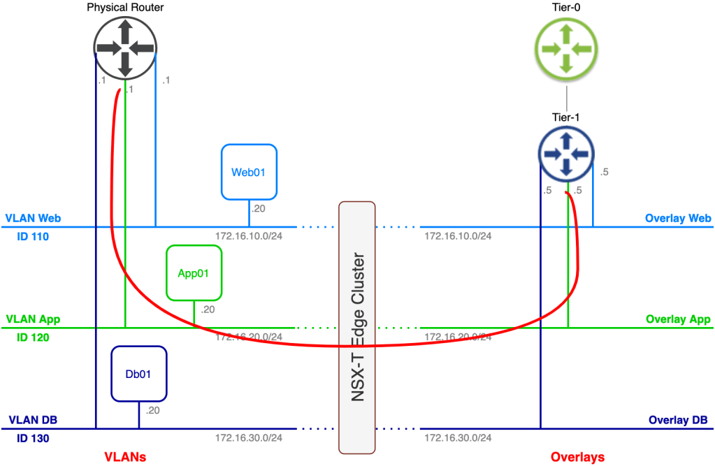
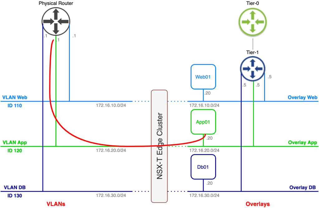
The current state of today’s lab environment from an application/network point of view looks something like this:
On the left side we have the legacy VLAN-based networks where a three tier application is connected. On the right side we have the NSX-T based overlay networks. Our task is to migrate the application to the NSX-T overlay without making any configuration changes to the application’s three virtual machines.
As you probably noticed some preparations have been made in advance. A Tier-1 gateway and three connected overlay segments have been created. The overlay segments match the VLAN structure and their respective IP subnets except for the default gateway of course.
This is a really good start, but we’re not quite there yet. Follow along as we configure the missing parts of our bridge.
Step 1 – Create Trunking Port Group
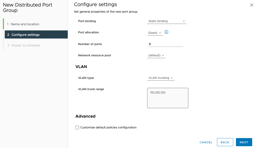
The first thing we need to do is create a port group that will carry traffic for the three VLANs that are in scope for bridging. For this scenario we create a vSphere distributed port group called “Bridge” that will be trunking VLANs 110, 120, and 130:
We need to set Promiscuous mode and Forged transmits on this port group to Accept:
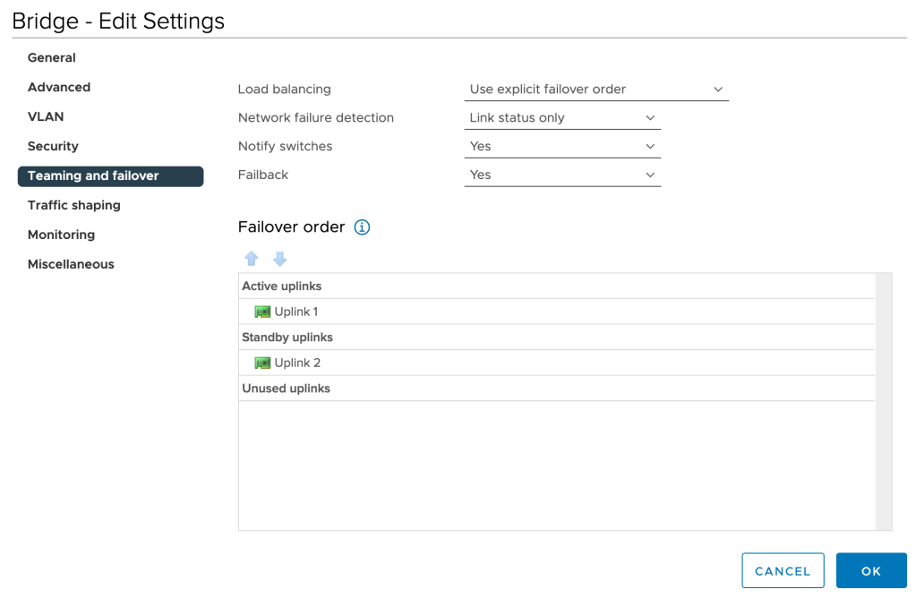
To keep things deterministic, we’ll change the Teaming and failover setting of this port group to explicit failover order with one active and one standby uplink:
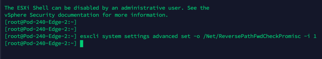
Lastly, on the ESXi hosts where the NSX-T Edge node virtual machines are running we must enable reverse filter by issuing the following esxcli command:
esxcli system settings advanced set -o /Net/ReversePathFwdCheckPromisc -i 1
After running the above command we need to disable/enable Promiscuous mode on the “Bridge” port group so that the reverse filter becomes active.
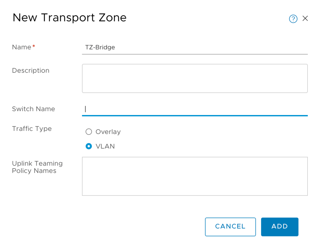
Step 2 – Create Bridge Transport Zone
Within NSX-T we create a new VLAN transport zone for bridging. Transport zones are managed under System > Configuration > Fabric > Transport Zones:
I’m calling this new transport zone “TZ-Bridge”.
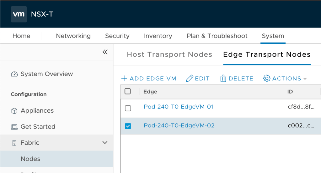
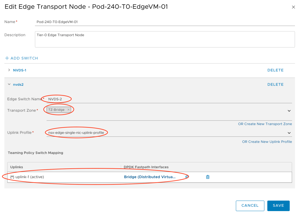
Step 3 – Add TZ-Bridge to Edge Nodes
A transport zone without transport nodes isn’t much of a transport zone. Bridging in NSX-T is done via the Edge transport nodes and therefore we must add the newly created “TZ-Bridge” transport zone to the Edge transport nodes.
Edge transport nodes are managed under System > Configuration > Fabric > Nodes > Edge Transport Nodes:
We edit each of the Edge transport nodes that will participate in bridging as follows:
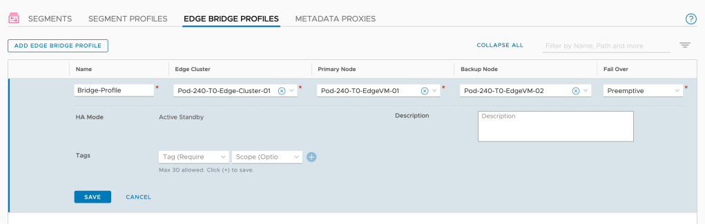
The Edge bridge profile is the NSX-T configuration construct that ties together the Edge bridge with the overlay segments that should be part of the bridge.
Navigate to Networking > Connectivity > Segments > Edge Bridge Profiles and create a new profile with the relevant settings:
Note that you configure a primary and a backup node for the bridge.
Step 5 – Configure Bridging on the Overlay Segments
We’re getting there. The final step is to configure the overlay segments for bridging.
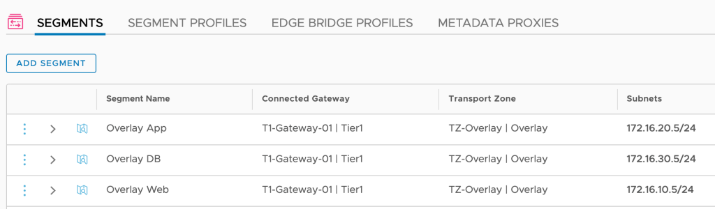
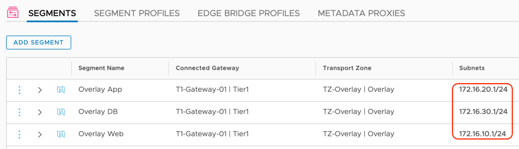
Navigate to Networking > Connectivity > Segments:
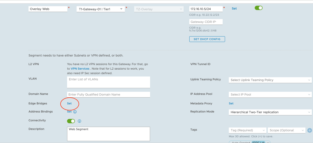
Here we modify the three overlay segments so they become part of the bridge. We begin with the “Overlay Web” segment and click the Set link for Edge Bridges:
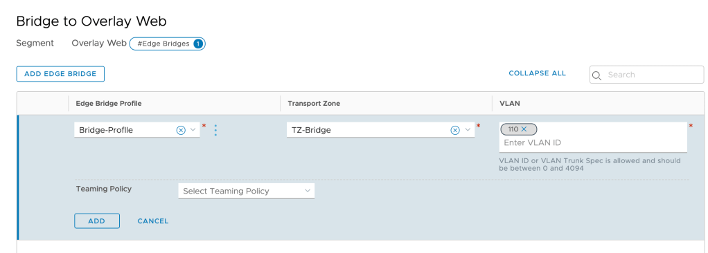
Click on Add Edge Bridge and in the next screen select the Edge bridge profile, the bridge transport zone and the VLAN ID of the corresponding VLAN (ID 110 in this case):
We repeat this step for the other two segments.
Verify Bridge
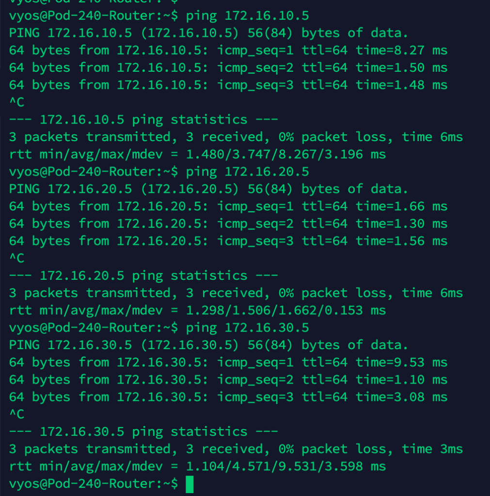
At this point we should have a working network bridge between the VLANs and the NSX-T overlay. To verify this we’ll perform a simple ping test from the physical router to each of the Tier-1 downlink interfaces.
We expect to receive replies from 172.16.10.5, 172.16.20.5, and 172.16.30.5:
Ping replies is a good thing!
Let’s have a look at the network path for a ping from the physical router App VLAN interface (172.16.20.1) to the Tier-1 App downlink interface (172.16.20.5):
Migrate Virtual Machines
With a working bridge in place there’s nothing stopping us from migrating the VMs to the overlay segments. So let’s just do that.
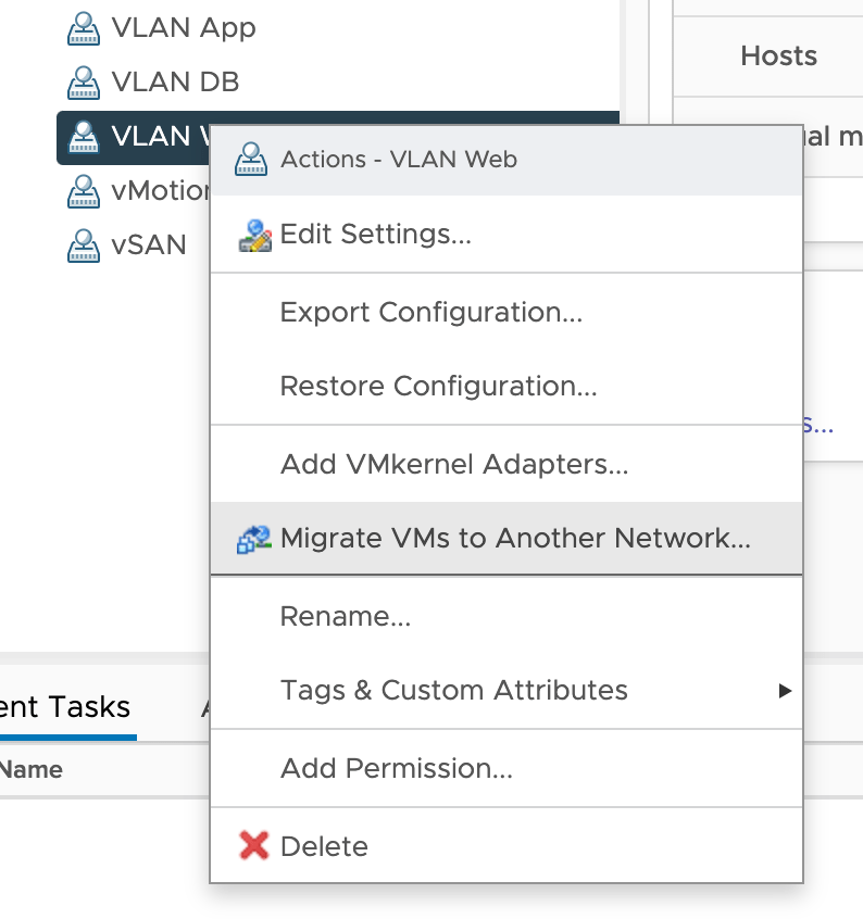
In vSphere Client, right click the VLAN port group you want to migrate from and choose Migrate VMs to Another Network:
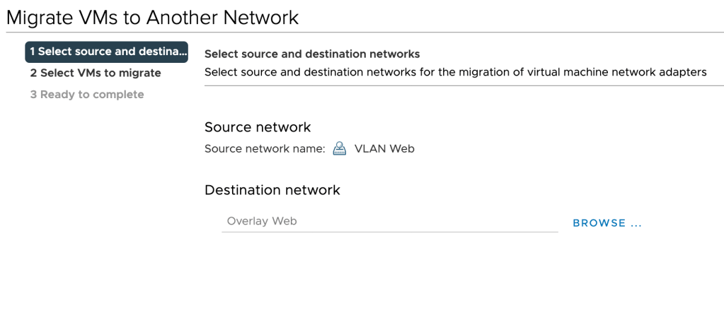
Choose the destination NSX-T overlay segment:
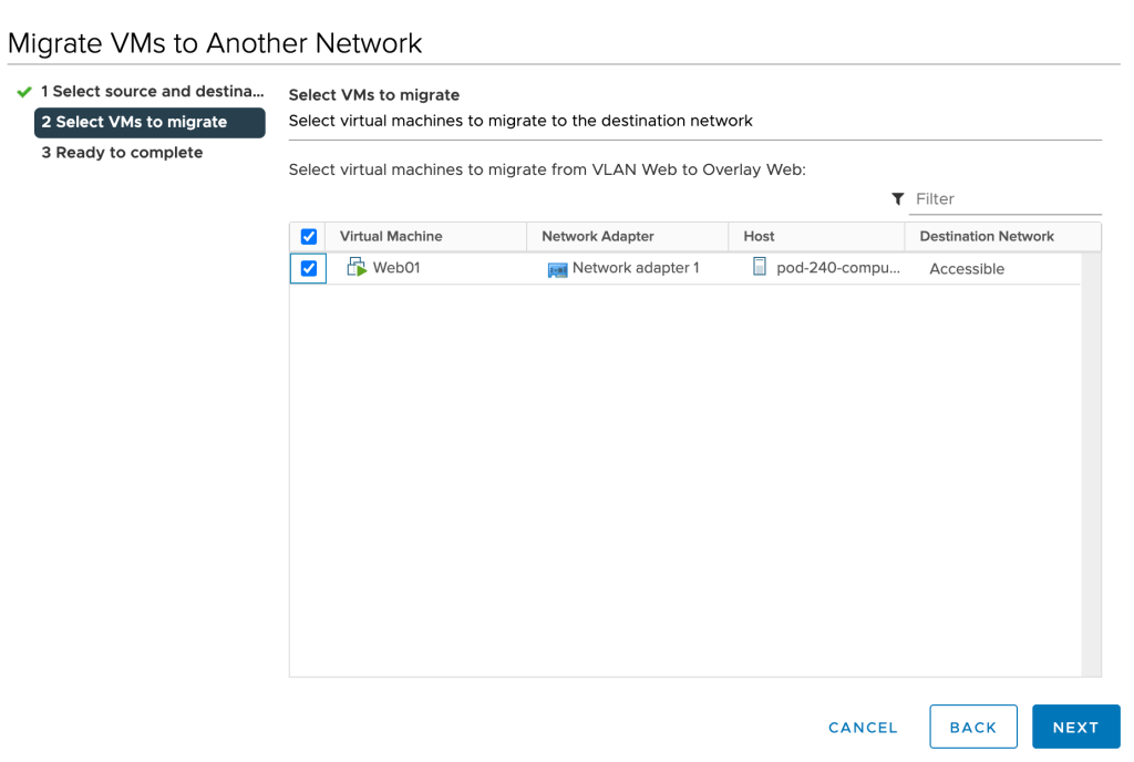
Select the VMs you want to migrate:
Click Next and Finish. Repeat these steps for the remaining virtual machines.
Verify Virtual Machine Networking
With the virtual machines now connected to the overlay segments, it’s probably a good time to verify that we can still reach these guys. Let’s run some pings from the physical router to the virtual machines this time:
That’s seems to be working. Let’s have another look at the network path for a ping from the physical router to the App01 virtual machine:
Cool!
Optimize Network Path
While we’ve successfully migrated our virtual machines to the NSX-T overlay, we still have that nasty hairpin.
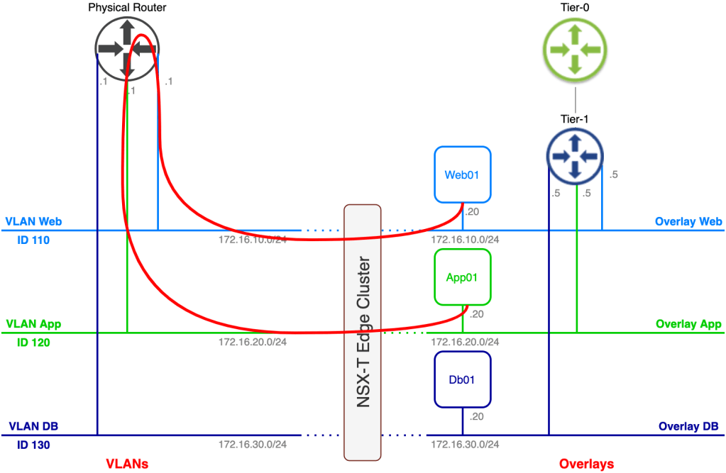
Let’s say Web01 needs to communicate with App01. With the current setup the network path for that traffic looks like this:
One of the reasons organizations implement NSX-T overlay is to get rid of “hairpinning” network traffic so obviously we can’t have it like this.
There are two things we can do here to mitigate the hairpin. I think that you figured it out already, but here they are:
Migrate the default gateway from the physical router to the Tier-1 Gateway
Change the default gateway within the VM guest OS
I personally prefer the first option. Using this option we don’t need to touch the guest OS and we also replace the physical router’s VLAN interface which is what we want to do most of the time once we emptied a VLAN.
In our scenario we weren’t allowed to change any configuration on the virtual machine which requires that we go for the first option. The process is pretty easy:
Shut down the physical router interface that is configured with the .1 IP address
Change the default gateway on the overlay segment from .5 to .1
After completing these steps we have achieved our goal. Using the same example as before where Web01 communicates with App01:
Much better. You might say that network traffic still hairpins through the Tier-1 gateway, and from a logical perspective it does. But the Tier-1 is a completely distributed router in this scenario (no stateful services) which means we don’t have an issue with that. With some luck Web01 and App01 are running on the same transport node and network traffic between the two never even hits the physical network.
Summary
In this article we had a closer look at configuring bridging between VLANs and the NSX-T overlay. Bridging is a useful tool in certain migration scenarios or in scenarios where layer 2 adjacency between a VM connected to the NSX-T overlay and something that isn’t is required.
Hopefully you found this post useful on your NSX journey.
Back in April I published a post about my GitHub repository containing Ansible scripts that perform automated deployment of nested vSphere/NSX-T lab environments.
A lot has happened during the last 5 months and now that we’re close to making version 2 the default branch, I thought it would be a good time to give you an update of what’s been going on.
The idea
Let’s start with the one thing that hasn’t changed, namely the idea behind this project: A collection of Ansible scripts that perform fully automated deployments of nested VMware SDDC Pods.
If you’re looking to deploy complete VMware SDDC nested environments without having to manually install all of the individual components, this project might be of interest to you.
No, you can’t make this work on an Intel NUC. You will probably need some real server hardware (and decent storage too), but if your goal is to spend quality time with the latest VMware technologies like vSphere 7 and NSX-T 3 (for studies, PoC, dev/test, etc), that investment will be worth it any time.
A partner in crime
Soon after publishing my second post about this project Luis Chanu, who already was somewhat of a “trusted advisor”, stepped up to become a lead developer himself. Having Luis as my script writing partner has made a tremendous impact on the direction this project has taken. For example, in v2 the entire code base got a major overhaul. Smarter, more scalable code and many other good improvements adding a certain level of maturity to the project. Most of this is thanks to Luis hard work during the last months.
The old project name wasn’t really a name anyway and quite a mouthful too. “SDDC.Lab” is more catchy and to the point. It also happens to be the default domain name for the SDDC Pods that you deploy (it’s configurable of course). We hope you like it too.
New components
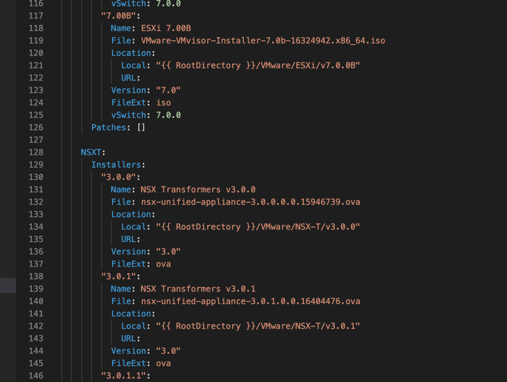
Alright. There are many new and improved things in version 2, but from a component perspective we have two new additions:
vRealize Log Insight
DNS Server (Ubuntu VM with ISC BIND)
We’re especially happy with the addition of that DNS server which also acts as an NTP server. With a zero-touch installation and pre-configured for any Pods that you will deploy, this thing will save you time and potential headaches. It is an optional component and you can still leverage your own DNS/NTP infrastructure if you want to, but we think that most people will want to include our “appliance”.
I don’t think that vRealize Log Insight needs any introduction. It’s VMware’s “syslog server on steroids” product and a very common component in VMware SDDCs. That’s why we added it to the project where it’s configured as the default syslog target.
Deploy to vCenter
Previously you were only able to deploy the nested Pods to standalone ESXi hosts. Just before freezing the code for the v2 release we managed to squeeze in the option to deploy Pods to a vCenter target. A very welcome addition that will make life easier for those with physical ESXi hosts managed by vCenter (not too uncommon I believe).
IPv6 support
In v2 the following components can be configured with IPv6:
Nested VyOS router (all interfaces)
NSX-T segments
NSX-T eBGP peering with the router
Ultimately we want to offer IPv6-only Pods and this is something that has high priority in upcoming releases.
Miscellaneous improvements
A lot of other things have improved and the majority of this is “behind the scenes” stuff. I do want to highlight a couple of them:
Utilize data structures (where possible) for improved scalability and manageability
An improved deployment process that decreases overall deployment time
Introduction of the software library where the required OVA/ISO files are stored
A separate data file for license keys which are then automatically applied during a Pod deployment
Utilize DDNS (nsupdate) for populating the DNS server with records
Many, many Ansible script optimizations
Trying out v2
As mentioned before, we are busy with finishing touches of version 2 (when our schedules allow us to). We believe that the code is pretty much done and are now mainly working on the documentation where there are still some gaps.
If you would like to give version 2 a try today you can start by visiting the branch’s page over at GitHub and basically take it from there. Don’t forget to do a “git checkout dev-v2” after cloning the repository as v2 is not the default branch yet. Update 6/11/2020: SDDC.Lab version 2 is now the default branch. Have fun!
The information in the README.md is almost complete and should help you get started. We’re also working on a “Deploying your first SDDC.Lab Pod” guide which is not complete yet but could still be helpful.
Let’s us know what you think or if you have any questions or suggestions.
And now something completely different. Recently, while working on a project, I had to come up with a way to automate Ubuntu Server 20.04 VM installations on vSphere. Utilizing Ubuntu’s new autoinstall method together with some Ansible code I managed to get something up and running. Decent enough to share it with you.
Overview
The Playbook I’m showcasing in this article will carry out the following operations:
Download the Ubuntu Server 20.04 ISO
Modify ISO contents to enable unattended installation
Upload the modified ISO to a vSphere datastore
Create a VM and install Ubuntu Server 20.04 using the modified ISO
Configure static IP on the Ubuntu Server
Step 5 is required because for some reason Ubuntu’s autoinstall reverts the network configuration to DHCP after rebooting the server. I hope this will be fixed in a future release.
Below are the contents of the Ansible Playbook for reference. This together with the supporting files is actually better viewed and cloned on Github.
---
- hosts: localhost
  name: DeployUbuntu.yml
  gather_facts: false
  vars:
    workingdir: "{{ lookup('env','HOME') }}/ubuntu-autoinstall"   # Temp directory on the Ansible Controller
    ubuntuiso: ubuntu-20.04.2-live-server-amd64.iso               # Ubuntu ISO filename
    ubuntuiso_url: http://old-releases.ubuntu.com/releases/20.04/ # Ubuntu ISO URL
    ubuntunewiso: ubuntu.iso                                      # Ubuntu custom ISO name
    vcenterserver: vcenter.demo.local                             # vCenter FQDN
    vcenteruser: administrator@vsphere.local                      # vCenter username
    vcenterpassword: VMware1!                                     # vCenter password
    datacenter: SDDC                                              # vCenter datacenter
    vspherecluster: Lab-Cluster                                   # vCenter cluster
    vmfolder: /                                                   # vCenter VM folder
    datastore: Shared_VMs                                         # vSphere datastore
    datastoredir: /ISO                                            # vSphere datastore ISO directory
    ubuntuvmname: ubuntu-server                                   # Ubuntu VM name of the virtual machine
    ubuntuvmdisksize: 50                                          # Ubuntu VM disksize in gigabytes
    ubuntuvmmemorysize: 2048                                      # Ubuntu VM memory size in megabytes
    ubuntuvvmcpus: 1                                              # Ubuntu VM number of CPUs
    ubuntuvmcpucores: 1                                           # Ubuntu VM number of cores
    ubuntuvmportgroup: VLAN-301                                   # Ubuntu VM vSphere portgroup
    ubuntuoslocale: en_US                                         # Ubuntu OS locale
    ubuntuoskeyboardlayout: en                                    # Ubuntu OS keyboard layout
    ubuntuoskeyboardvariant: us                                   # Ubuntu OS keyboard variant
    ubuntuosipv4address: 10.203.0.50/24                           # Ubuntu OS IPv4 address
    ubuntuosipv4gateway: 10.203.0.1                               # Ubuntu OS IPv4 gateway
    ubuntuosipv4dns: 10.203.0.5                                   # Ubuntu OS DNS server
    ubuntuossearchdomain: sddc.lab                                # Ubuntu OS DNS search domain
    ubuntuoshostname: ubbuntu-server                              # Ubuntu OS hostname
    ubuntuosuser: ubuntu                                          # Ubuntu OS username
    ubuntuospassword: VMware1!                                    # Ubuntu OS password

  tasks:
    - name: Create working directory on Ansible Controller
      ansible.builtin.file:
        path: "{{ workingdir }}"
        state: directory
        mode: "755"


    - name: Check if ubuntu ISO exists locally on Ansible Controller
      ansible.builtin.stat:
        path: "{{ workingdir }}/{{ ubuntuiso }}"
      register: installerfilecheck


    - name: Download ubuntu ISO (if ISO file doesn't exist locally)
      ansible.builtin.get_url:
        url: "{{ ubuntuiso_url }}{{ ubuntuiso }}"
        dest: "{{ workingdir }}/{{ ubuntuiso }}"
        mode: "755"
      when:
        - not installerfilecheck.stat.exists


    - name: Extract Ubuntu ISO
      ansible.builtin.command: "xorriso -osirrox on -indev {{ workingdir }}/{{ ubuntuiso }} \
                               -extract / {{ workingdir }}/iso"
      changed_when: false


    - name: Add write permission to extracted files
      ansible.builtin.command: "chmod -R +w {{ workingdir }}/iso"    # Using chmod as Ansible (Python) can't handle the recursion depth on the Ubuntu ISO
      changed_when: false


## Start workaround issue with Ubuntu autoinstall
## Details of the issue and the workaround: https://askubuntu.com/questions/1394441/ubuntu-20-04-3-autoinstall-with-embedded-user-data-crashing-i-got-workaround

    - name: Extract the Packages.gz file on Ubuntu ISO
      ansible.builtin.command: "gunzip -f {{ workingdir }}/iso/dists/focal/main/binary-amd64/Packages.gz --keep"
      changed_when: false

## End workaround issue with Ubuntu autoinstall


    - name: Copy txt.cfg from ubuntu ISO
      ansible.builtin.copy:
        src: "{{ workingdir }}/iso/isolinux/txt.cfg"
        dest: "{{ workingdir }}/isocopy/isolinux/"
        mode: "775"


    - name: Edit txt.cfg to modify append line
      ansible.builtin.replace:
        dest: "{{ workingdir }}/isocopy/isolinux/txt.cfg"
        regexp: 'append   initrd=/casper/initrd quiet  ---'
        replace: 'append   initrd=/casper/initrd quiet --- autoinstall ds=nocloud;s=/cdrom/autoinstall/'


    - name: Create directory to store user-data and meta-data
      ansible.builtin.file:
        path: "{{ workingdir }}/isocopy/autoinstall"
        state: directory
        mode: "755"


    - name: Copy user-data file to directory
      ansible.builtin.template:
        src: ./Ubuntu_user-data.j2
        dest: "{{ workingdir }}/isocopy/autoinstall/user-data"
        mode: "755"


    - name: Create empty meta-data file in directory
      ansible.builtin.file:
        path: "{{ workingdir }}/isocopy/autoinstall/meta-data"
        state: touch
        mode: "755"


    - name: Create custom ubuntu ISO
      ansible.builtin.command: "xorrisofs -relaxed-filenames -J -R -o {{ workingdir }}/{{ ubuntunewiso }} \
                               -b isolinux/isolinux.bin -c isolinux/boot.cat -no-emul-boot -boot-load-size 4 -boot-info-table \
                               {{ workingdir }}/iso/ {{ workingdir }}/isocopy/"
      args:
        chdir: "{{ workingdir }}/isocopy/"
      changed_when: false


    - name: Upload the custom ubuntu ISO to the vSphere datastore
      community.vmware.vsphere_copy:
        hostname: "{{ vcenterserver }}"
        username: "{{ vcenteruser }}"
        password: "{{ vcenterpassword }}"
        validate_certs: false
        datacenter: "{{ datacenter }}"
        src: "{{ workingdir }}/{{ ubuntunewiso }}"
        datastore: "{{ datastore }}"
        path: "{{ datastoredir }}/{{ ubuntunewiso }}"


    - name: Deploy ubuntu VM
      community.vmware.vmware_guest:
        hostname: "{{ vcenterserver }}"
        username: "{{ vcenteruser }}"
        password: "{{ vcenterpassword }}"
        validate_certs: false
        name: "{{ ubuntuvmname }}"
        state: poweredon
        guest_id: ubuntu64Guest
        cluster: "{{ vspherecluster }}"
        datacenter: "{{ datacenter }}"
        folder: "{{ vmfolder }}"
        disk:
          - size_gb: "{{ ubuntuvmdisksize }}"
            type: thin
            datastore: "{{ datastore }}"
        hardware:
          memory_mb: "{{ ubuntuvmmemorysize }}"
          num_cpus: "{{ ubuntuvvmcpus }}"
          num_cpu_cores_per_socket: "{{ ubuntuvmcpucores }}"
          scsi: paravirtual
        networks:
          - name: "{{ ubuntuvmportgroup }}"
            device_type: vmxnet3
        cdrom:
          - controller_number: 0
            unit_number: 0
            type: iso
            iso_path: "[{{ datastore }}] {{ datastoredir }}/{{ ubuntunewiso }}"
            state: present
        annotation: |
                    *** Auto-Deployed by Ansible ***
                    Username: {{ ubuntuosuser }}
                    Password: {{ ubuntuospassword }}


    - name: Start checking if the ubuntu VM is ready
      community.vmware.vmware_guest_info:
        hostname: "{{ vcenterserver }}"
        username: "{{ vcenteruser }}"
        password: "{{ vcenterpassword }}"
        datacenter: "{{ datacenter }}"
        validate_certs: false
        name: "{{ ubuntuvmname }}"
        schema: vsphere
      register: vm_facts
      until: vm_facts.instance.guest.hostName is search(ubuntuoshostname)
      retries: 30
      delay: 60


    - name: Set password for the ubuntu user
      community.vmware.vmware_vm_shell:
        hostname: "{{ vcenterserver }}"
        username: "{{ vcenteruser }}"
        password: "{{ vcenterpassword }}"
        validate_certs: false
        vm_id: "{{ ubuntuvmname }}"
        vm_username: "{{ ubuntuosuser }}"
        vm_password: VMware1!
        vm_shell: /usr/bin/echo
        vm_shell_args: "'{{ ubuntuosuser }}:{{ ubuntuospassword }}' | sudo chpasswd"


    - name: Copy network configuration file to working directory
      ansible.builtin.template:
        src: ./ubuntu_Netplan.j2
        dest: "{{ workingdir }}/00-installer-config.yaml"
        mode: "755"


    - name: Copy network configuration file to ubuntu VM
      community.vmware.vmware_guest_file_operation:
        hostname: "{{ vcenterserver }}"
        username: "{{ vcenteruser }}"
        password: "{{ vcenterpassword }}"
        validate_certs: false
        vm_id: "{{ ubuntuvmname }}"
        vm_username: "{{ ubuntuosuser }}"
        vm_password: VMware1!
        copy:
          src: "{{ workingdir }}/00-installer-config.yaml"
          dest: "/home/{{ ubuntuosuser }}/00-installer-config.yaml"


    - name: Move network configuration file to right location on ubuntu VM
      community.vmware.vmware_vm_shell:
        hostname: "{{ vcenterserver }}"
        username: "{{ vcenteruser }}"
        password: "{{ vcenterpassword }}"
        validate_certs: false
        vm_id: "{{ ubuntuvmname }}"
        vm_username: "{{ ubuntuosuser }}"
        vm_password: VMware1!
        vm_shell: /usr/bin/sudo
        vm_shell_args: "mv /home/{{ ubuntuosuser }}/00-installer-config.yaml /etc/netplan/00-installer-config.yaml"


    - name: Appply the network configuration on ubuntu VM
      community.vmware.vmware_vm_shell:
        hostname: "{{ vcenterserver }}"
        username: "{{ vcenteruser }}"
        password: "{{ vcenterpassword }}"
        validate_certs: false
        vm_id: "{{ ubuntuvmname }}"
        vm_username: "{{ ubuntuosuser }}"
        vm_password: VMware1!
        vm_shell: /usr/bin/sudo
        vm_shell_args: netplan apply


    - name: Delete working directory on Ansible Controller
      ansible.builtin.file:
        path: "{{ workingdir }}"
        state: absent
Most of the tasks here are pretty self-explanatory. I’ve also tried to use descriptive names for each task to help you understand what is happening.
You will change some of the values of the variables defined under vars: so that they match your environment. Besides that it’s pretty much good to go.
Usage
Modify DeployUbuntu.yml so that the values of the variables match your environment and requirements:
Now run the Playbook with:
ansible-playbook DeployUbuntu.yml
The deployment kicks off and will take about 15 minutes depending on your environment:
And the result is a shiny new Ubuntu Server 20.04 VM:
Not too hard. If Ubuntu’s autoinstall would leave the networking configuration in place after reboot, I would be able to shave off 5 tasks and more than 10 minutes from this deployment. Perhaps somebody out there already knows of a way to handle this? Let me know in the comments.
Summary
In this article I showcased a very basic single-purpose Ansible Playbook for unattended deployment of an Ubuntu Server 20.04 VM on VMware vSphere. This can of course be expanded upon and become part of a larger (automation) process. Hopefully you’ll find this useful and can serve as some inspiration for your projects.
NSX-T 3.0 comes with brand new features for logical networking in multisite environments. With NSX-T Federation the platform effectively receives a location-aware management, control, and data plane and this gives us, the implementers and architects, some very interesting new options when designing and installing NSX-T 3.0 in a multisite scenario.
Although Federation affects all major components of the NSX-T platform, in today’s article I want to have a closer look at a relatively basic, yet very common and popular use case: setting up stretched logical networking.
It’s going to be quite an exercise so let’s get right to it!
The environment
In this greenfield scenario we’ve been given access to two new data centers:
Both DCs are running vSphere 7 with a dedicated cluster for the customer’s workloads and another for the NSX-T Edge. Local Managers have been installed in each DC and ESXi hosts in the Compute Clusters have been configured as transport nodes. Edge Nodes have been deployed and are part of an NSX-T Edge Cluster. Transport zones for VLAN, overlay and Edge have been created, but apart from that no other logical networking has been configured.
The assignment
The customer wants us to set up a stretched logical network between the Stockholm and Copenhagen data centers so that workloads can connect to the same logical network regardless of their physical location. Local egress should be implemented so that northbound network traffic egresses via the nearest physical router.
The implementation
Time to get our hands dirty and find out what it takes to get this up and running.
Step 1 – Deploy Global Manager
NSX-T Global Manager is a new component in NSX-T 3.0 and required when setting up Federation. In Federation the Global Manager is the central point of administration pushing configuration to the relevant Local Managers.
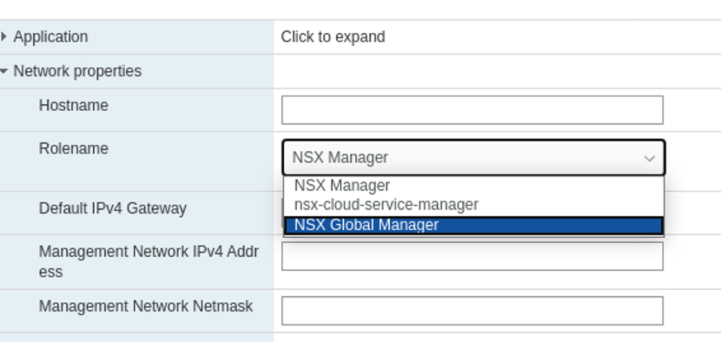
A Global Manager is deployed from the same OVA that is used to deploy a Local Manager. We just select the NSX Global Manager role in the deployment wizard:
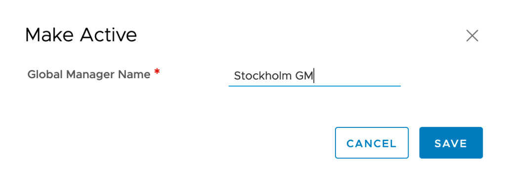
After installing the Global Manager in the Stockholm data center we need to activate it. This is done in the Global Manager UI under System > Configuration > Location Manager > Global Manager:
And we have an active Global Manager in the Stockholm DC:
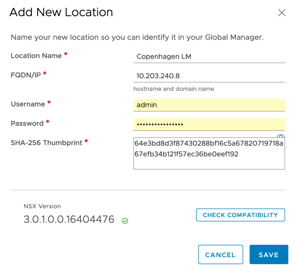
Step 2 – Add locations
With the Global Manager alive and kicking we can start adding the Local Managers. This is done under System > Configuration > Location Manager > Locations:
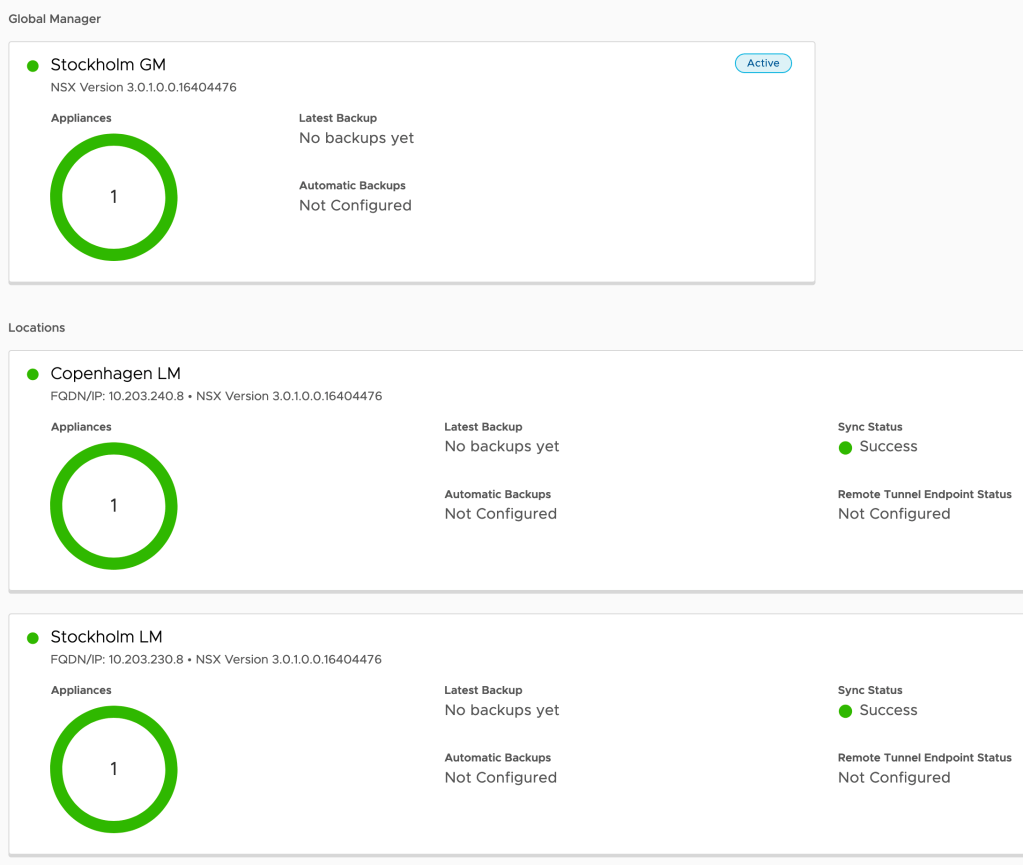
Once the Local Managers for Stockholm and Copenhagen are added to the Global Manager we have this nice looking overview in the Global Manager UI:
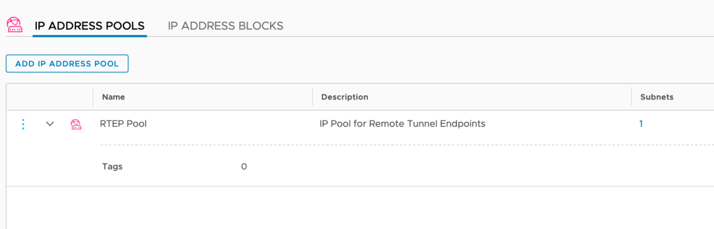
Step 3 – Create IP pools for RTEP
We need an IP pool in each location that provides IP addresses to the RTEP interfaces on the Edge Nodes. In each Local Manager UI navigate to Networking > IP Management > IP Address Pools and add a new IP pool:
Note: With NSX-T Federation we need an additional VLAN per location for RTEP.
Step 4 – Configure Edge Nodes
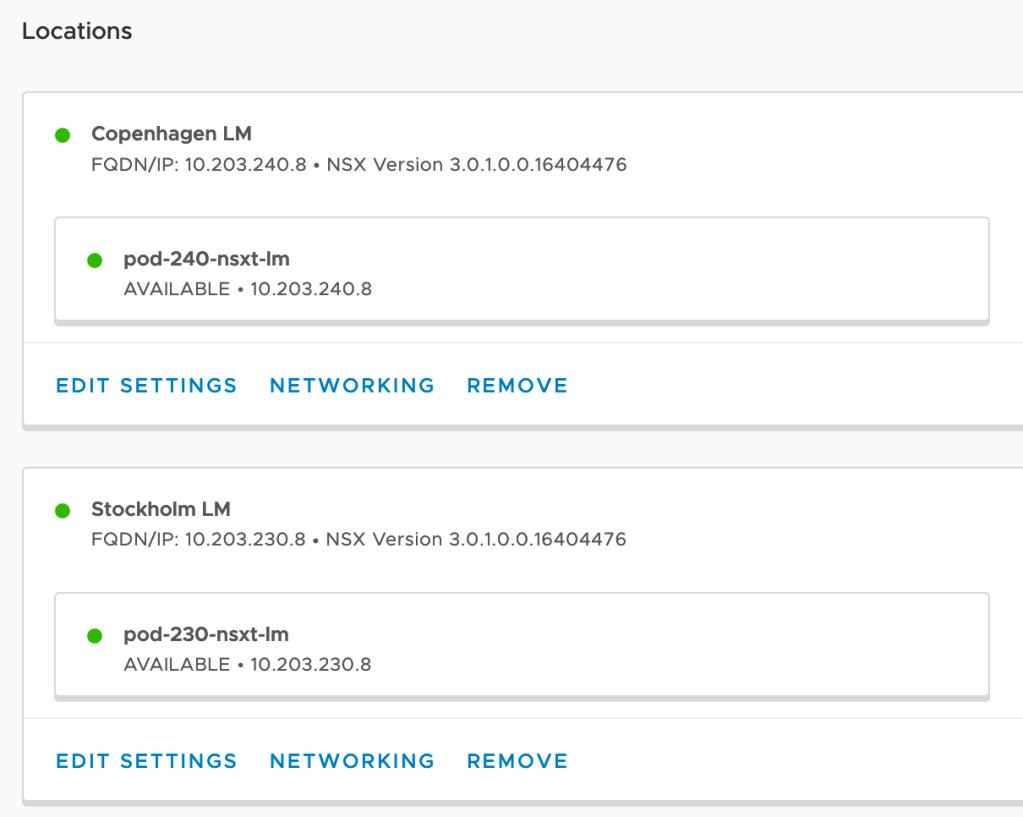
The Edge Nodes need to be configured for stretched networking. This task is initiated from the Global Manager, but the actual configuration is done on each of the Local Managers.
From the Global Manager UI we navigate to System > Configuration > Location Manager > Locations:
For each of the locations we click Networking:
The existing NSX-T Edge Cluster is detected and Global Manager proposes we use it for inter-location communication. In this case that’s indeed what we want so let’s click the “Configure” button and find out what happens:
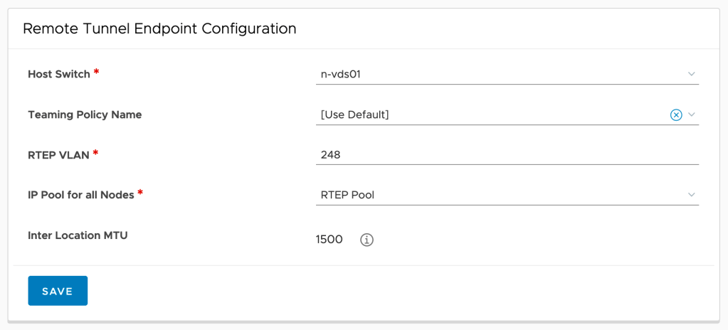
We’re directed to the Local Manager where I’m selecting both Edge Nodes and fill out the “Remote Tunnel Endpoint Configuration” form.
We repeat this process for the other location.
Step 5 – Create stretched Tier-0 Gateway
Now things are starting to get interesting. We’re about to deploy a stretched Tier-0 Gateway, but before we do we first need to create Tier-0 uplink segments for each location.
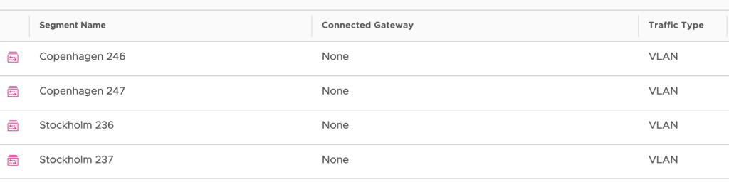
Segments
These are created from the Global Manager UI under Networking > Connectivity > Segments:
Note that these are VLAN-backed segments. Make sure that you pick the right location and corresponding VLAN ID when creating the uplink segments.
Tier-0 configuration
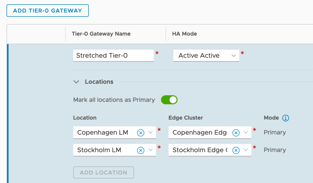
Now let’s get the stretched Tier-0 Gateway up and running. In the Global Manager UI navigate to Networking > Connectivity > Tier-0 Gateways and click the Add Tier-0 Gateway:
As you can see I’m configuring this Tier-0 with Active-Active HA Mode and also enable it to be primary at all locations. This means is that each site will utilize their local Tier-0 SR/DR components running on the local Edge Nodes. In other words we are configuring local egress. Without enabling “Mark all locations as Primary” we would configure central egress.
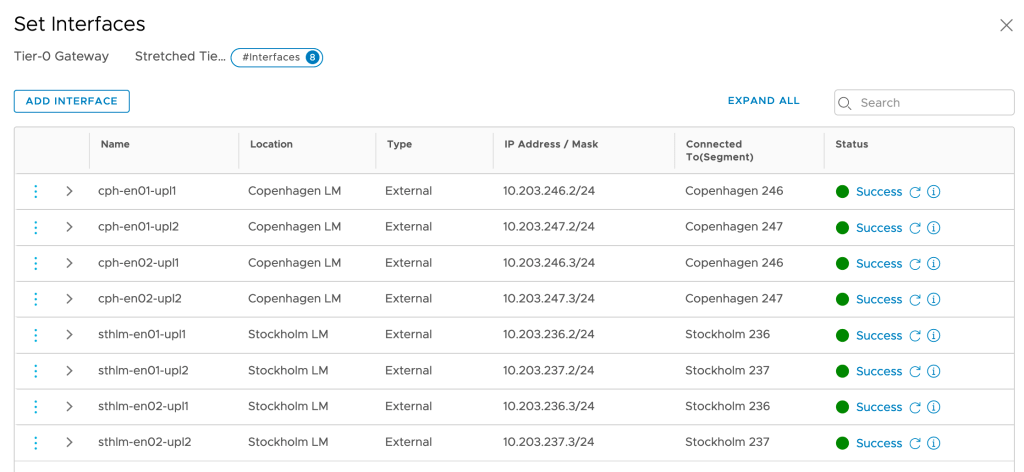
Tier-0 interfaces
The Tier-0 SR components at each site need connectivity with the physical network. This is achieved by creating Tier-0 external interfaces. In this scenario both Stockholm and Copenhagen will “contribute” with four Tier-0 external interfaces:
Adding these interfaces is a delicate job. Especially when working with a stretched Tier-0 Gateway you need to make sure that you pick the right location, configure the right IP address, and select the right uplink segment.
Tier-0 routing
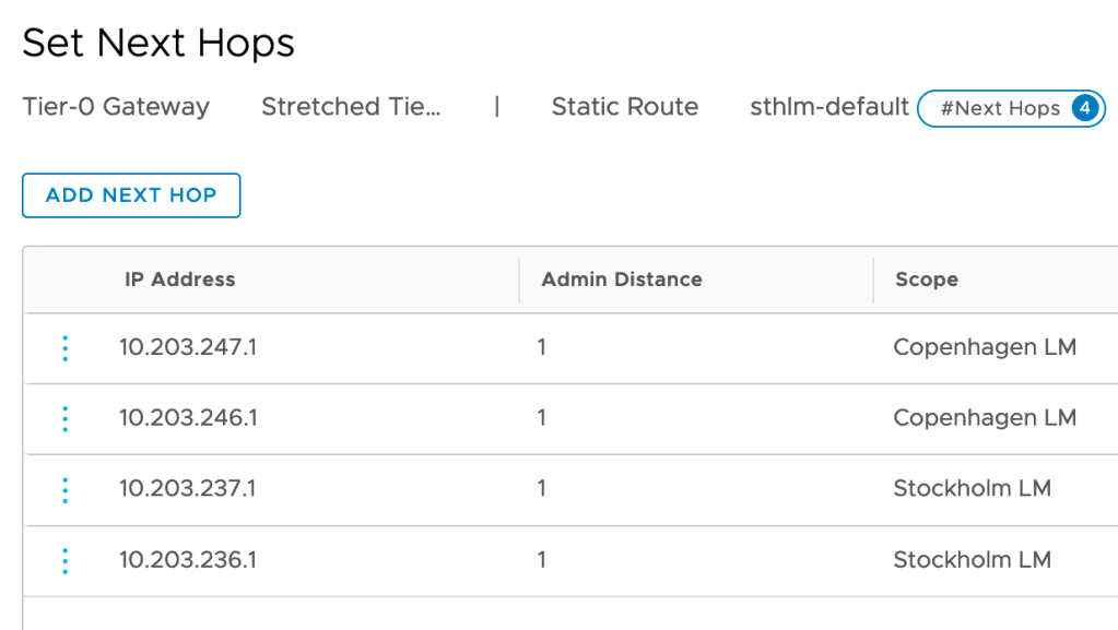
A Tier-0 that ain’t routing ain’t a Tier-0 goes the saying. I’m going to start with configuring some default routes pointing to the physical network so that the workloads can find their way out of NSX-T:
Note that static routes now have the “Scope” attribute which is instructing the Tier-0 to apply a static route only where it’s relevant.
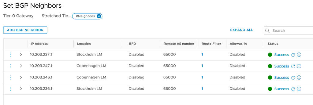
Next, I’m setting up BGP routing between the stretched Tier-0 and each site’s physical routers/ToRs:
As you can see BGP neighbor entries are also tied to a location.
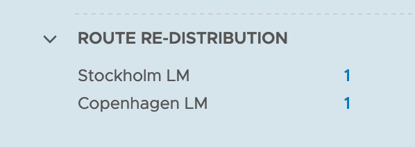
The last thing I’m setting up is route re-distribution which, again, is configured per location:
We now have a stretched Tier-0 instance up and running!
Step 6 – Create stretched Tier-1 Gateway
Creating a stretched Tier-1 Gateway is a straightforward process. From the Global Manager UI navigate to Networking > Connectivity > Tier-1 Gateways > Add Tier-1 Gateway:
There’s not that much to explain here. The stretched Tier-1 is linked to the stretched Tier-0. I also enable route advertisement for all connected segments so that the Tier-0 and physical network will know how to get to them.
Step 7 – Created stretched overlay segment
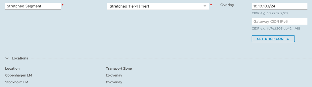
Finally, here comes the stretched overlay segment. This is the moment we’ve all been waiting for. In the Global Manager UI navigate to Networking > Connectivity > Segments > Add Segment:
Again, a very straightforward process. I’m attaching the stretched overlay segment to the stretched Tier-1 which is linked to the stretched Tier-0.
Step 8 – Connect workloads
Now that we have a stretched logical network available in both Stockholm and Copenhagen, it’s time to connect a workload or two and see if all our hard work has actually been of any use.
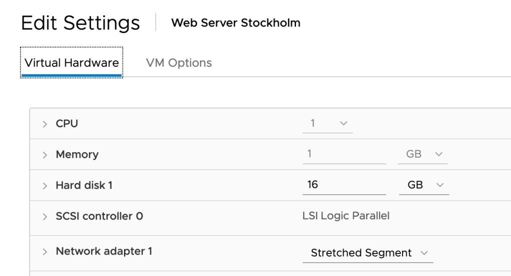
In Stockholm’s vCenter I connect a VM called “Web Server Stockholm” (IP address 10.10.10.100/24) to the “Stretched Segment” NSX port group:
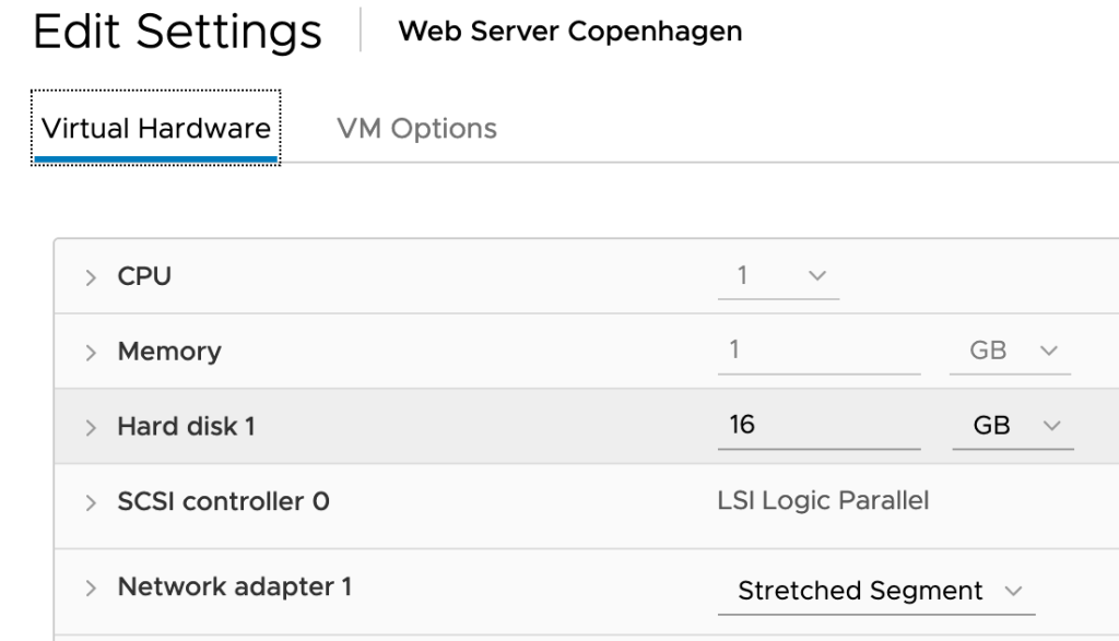
In Copenhagen I’m doing the same thing for a VM called “Web Server Copenhagen” (IP address 10.10.10.200/24):
We now have two workloads connected to the stretched logical network. Each of them located at a different site.
Review
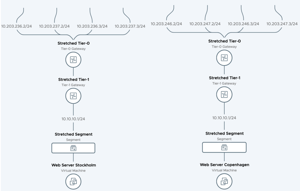
Let’s have a brief look at what we’ve been building. Starting with the Network Topology map produced by the Local Managers in Stockholm and Copenhagen:
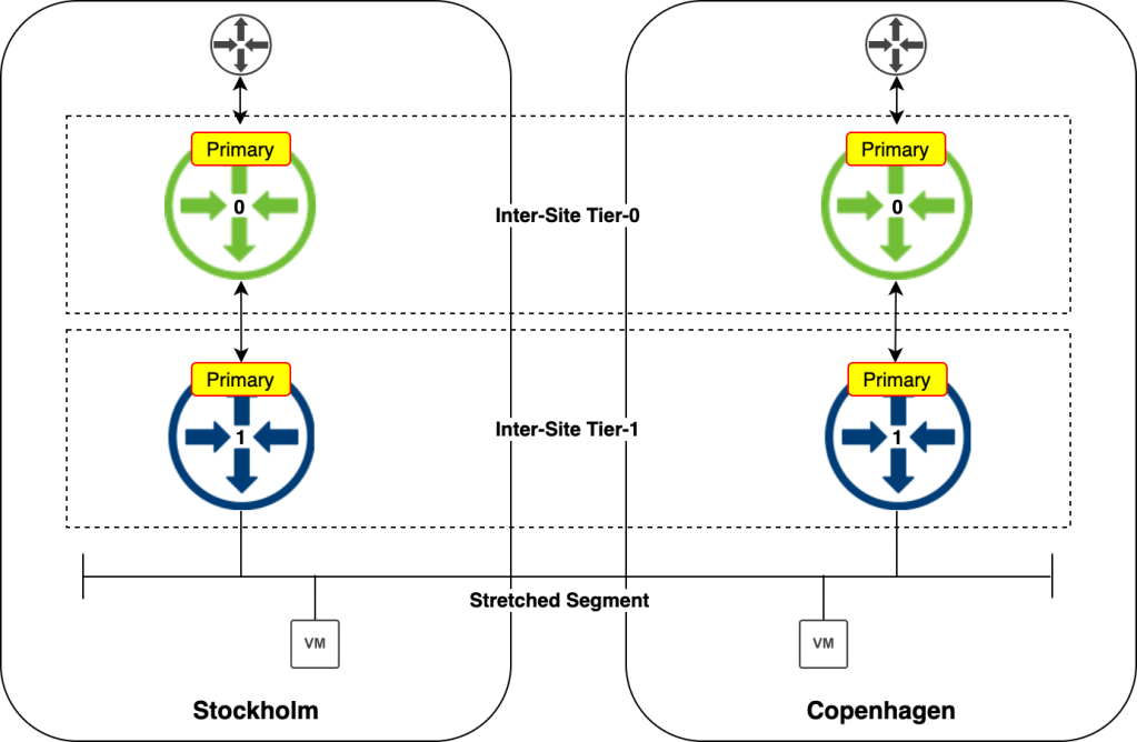
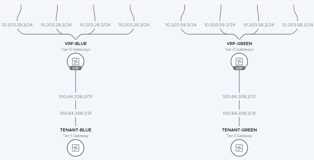
The following diagram shows things from an inter-site routing perspective:
The logical router components are primary in each DC which, as mentioned, enables local egress. Keep in mind that local egress comes with its own set of challenges (not controlled by NSX-T) and is not always desired.
Verify
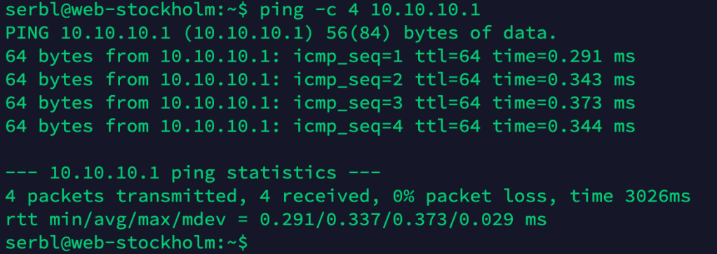
Verification is best done from the workloads running in the different data centers. Let’s start with the VM in Stockholm pinging the VM in Copenhagen:
That seems to be working fine. Now let’s have the Stockholm VM ping its default gateway (the Tier-1):
Very nice and a pretty low latency as well. Let’s now run a traceroute from the VM in Stockholm to a physical server:
The path from the Stockholm VM to the physical server is via the Tier-1 (10.10.10.1) over the router-link to the Tier-0 (100.64.176.0) then to the physical router in Stockholm (10.203.236.1) and from there to the destination (10.203.0.5).
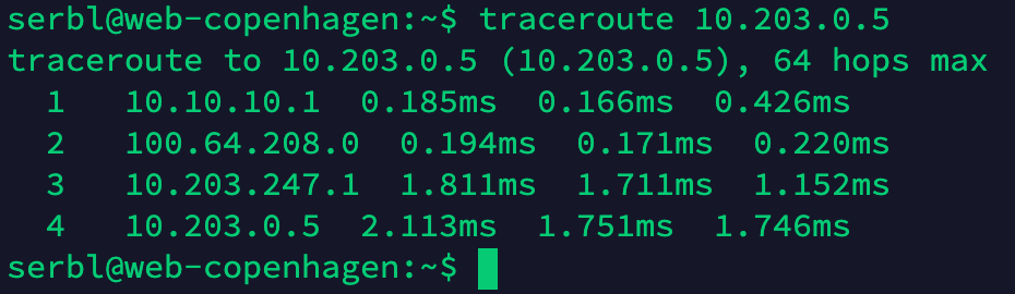
Let’s do the same traceroute exercise from the VM in Copenhagen:
So here we can see that the path goes from the Tier-1 (10.10.10.1) over the router-link to the Tier-0 (100.64.208.0) then to the physical router in Copenhagen (10.203.247.1) and from there to the destination (10.203.0.5).
So these simple traceroutes tell us that connectivity between the Tier-0 and the physical network is operational and that local egress is doing its thing with traffic is egressing through each site’s local physical router.
Summary
It’s been a battle, but it was worth it, right?
NSX-T Federation is an extremely welcome addition to the platform. Already in this early release it’s making things so much easier and more beautiful from a lot of perspectives. Designing and implementing multisite NSX-T just became fun again and undoubtedly many customers will start looking at implementing Federation in their multisite environments.
NSX-T version 3.0 brings a new routing construct to the table: VRF Lite. With VRF Lite we are able to configure per tenant data plane isolation all the way up to the physical network. Creating dedicated tenant Tier-0 Gateways for this particular use case is now a thing of the past!
With 100 VRFs per Tier-0 Gateway we’re also looking at a quite substantial improvement from a scalability point of view.
A closer look
VRF Lite in NSX-T 3.0 has the following main features and characteristics:
Each VRF maintains its own routing table.
A VRF acts as a virtual Tier-0 Gateway associated with a “parent” Tier-0 Gateway.
Inter-VRF traffic is either routed through the physical fabric or directly by using static routes.
As a child object of a Tier-0 Gateway, the VRF inherits some attributes and configuration from its parent. Edge cluster, HA mode, BGP local AS number, and BGP graceful restart settings are inherited and can’t be changed at the VRF level. All other configuration is managed independently within the VRF. This includes external interfaces, BGP state, BGP neighbors, routes, route filters, route redistribution, NAT, and Edge firewall.
Caveats
There are some things to keep in mind when working with NSX-T VRF Lite:
Bandwidth is shared across all Tier-0 Gateways and VRFs.
The Tier-0 Gateway’s HA mode (A/A or A/S) is inherited by the VRF. This is an important consideration when talking stateful services on the VRF level.
Inter-SR routing for VRF routing instances is not possible today.
Inter-VRF static routing does not work with NAT. Route through the physical fabric instead.
Not too bad.
Setting up VRF Lite
Let’s have a look at how to set up VRF Lite for two new tenants: Blue and Green.
In this simple walkthrough the assumption is that a Tier-0 Gateway with external interfaces is already configured. BGP should be enabled but peering or neighbor entries are not required. As a reference, in my lab environment the starting point looks like this:
A Tier-0 Gateway configured with Active/Standby HA mode and four external interfaces (two per Edge node) connecting it to the two ToRs.
Step 1 – Create VLAN segments
Just like its parent, a VRF needs VLAN-based uplink segments for establishing connectivity with the physical network:
Note that we configure a VLAN range indicating that the segment will be trunking VLANs within that range. Trunking segments are required for VRF uplinks.
In total we create four uplink segments for our two VRFs:
Segment
VLAN range
Uplink Teaming Policy
seg-blue-ext-01
1-50
teaming-1
seg-blue-ext-02
1-50
teaming-2
seg-green-ext-01
51-100
teaming-1
seg-green-ext-02
51-100
teaming-2
The uplink teaming policies make sure that traffic from each segment is steered towards specific Edge node N-VDS uplinks. This is done to establish a deterministic routing path.
Step 2 – Create the VRFs
Creating VRFs in NSX Manager is done under Networking > Connectivity > Tier-0 Gateways > Add Gateway > VRF:
When creating a VRF we initially only need to specify a name and a parent Tier-0 Gateway:
After repeating this process for the “Green” VRF we have our two VRFs as well as the Tier-0 Gateway in place:
Are we done now? No.
Step 3 – Create VRF external interfaces
Just like Tier-0 Gateways, VRFs need external interfaces to connect to the physical network.
In this scenario each VRF is configured with four external interfaces as specified in the table below:
VRF
Interface Name
IP Address
Segment
Access VLAN
Blue
en01-uplink1
10.203.28.2/24
seg-blue-ext-01
28
Blue
en01-uplink2
10.203.29.2/24
seg-blue-ext-02
29
Blue
en02-uplink1
10.203.28.3/24
seg-blue-ext-01
28
Blue
en02-uplink2
10.203.29.3/24
seg-blue-ext-02
29
Green
en01-uplink1
10.203.58.2/24
seg-green-ext-01
58
Green
en01-uplink2
10.203.59.2/24
seg-green-ext-02
59
Green
en02-uplink1
10.203.58.3/24
seg-green-ext-01
58
Green
en02-uplink2
10.203.59.3/24
seg-green-ext-02
59
As you remember, the segments that the external interfaces connect into are configured as trunk segments. Therefore we use the “Access VLAN” property on the VRF external interfaces to specify the BGP peering VLANs.
Step 4 – Configure BGP
With the L2 connectivity in place we can move our focus to L3. As stated earlier, VRFs inherit their BGP local AS number and some other BGP settings from their parent Tier-0, but BGP neighbor configuration is done within each VRF.
Configuring BGP neighbors within a VRF is done exactly the same way as on a Tier-0 Gateway:
There’s not much to explain here. In this particular scenario each VRF gets two BGP neighbor entries (one for each ToR):
Once the neighbor configurations are in place we can have a look at things from the Edge node CLI:
get logical-router
Here we see the two VRFs that we just configured.
After connecting a Tier-1 Gateway to each of the VRFs we can see that DR components are being instantiated for the VRFs:
get logical-router
From within a VRF context we can check things like the BGP neighbor status:
vrf 5
get bgp neighbor summary
And the BGP routing table for this particular VRF:
get bgp ipv4
Inevitably, VRFs add some complexity to NSX-T Edge routing. I recommend using the Network Topology map in NSX Manager which is a pretty nice tool for keeping an overview of the routing configuration:
Summary
The new VRF Lite feature introduced in NSX-T 3.0 is a great addition to the platform. It gives customers scalable data plane isolation all the way into the physical network. VRF Lite is easy to set up and maintain and will definitely become the go-to configuration in NSX-T multitenancy environments.